Motor installation – E-flite Eratix 3D 25e ARF User Manual
Page 11
11
E-flite Eratix 3D 25e ARF Assembly Manual
Motor Installation
Required Parts
• Fuselage assembly
• 4-40 blind nut (4)
• Hook and loop strap (2)
• Cowling
• 2
1
/
2
-inch (64mm) spinner
• Propeller
• Brushless ESC
• 4-40 x 3/8-inch socket head screws
• Hook and loop tape, 3-inch (76mm) (2)
• 2mm x 10mm sheet metal screw (4)
Required Tools and Adhesives
• Hex wrench: 3/32-inch
• Drill
• Phillips screwdriver #0
• Drill bit: 1/16 in (1.5mm)
Note: The firewall incorporates our new adjustable
mount system, enabling the modeler to install a variety of
outrunner motors.
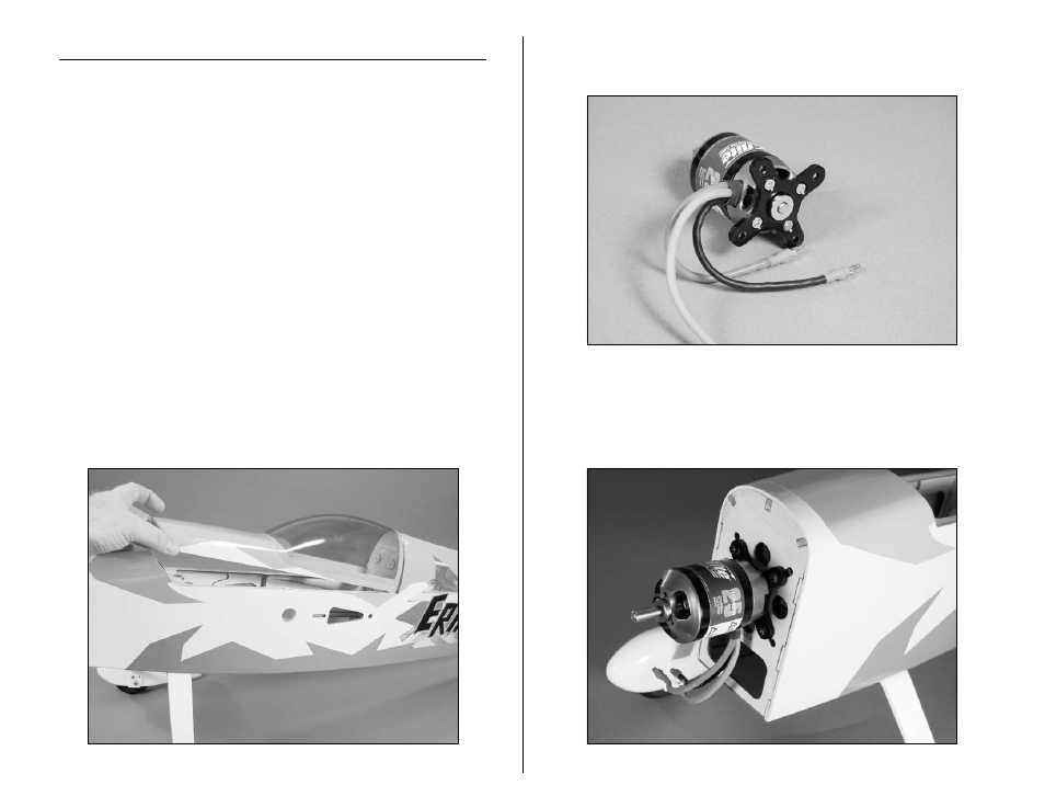
1. Remove the hatch from the fuselage by lifting up at the
front of the hatch. The hatch is held at the front using a
magnet, and the rear using dowels.
2. Attach the mount to the motor using the hardware
provided with the motor.
3. Use four 4-40 x 3/8-inch socket head screws to secure
the motor to the firewall. The blind nuts installed behind
the firewall can be moved to allow for the mounting of
various sizes of motors.
- Habu 32x DF ARF (84 pages)
- A6M5 Zero 300 BNF Basic (17 pages)
- Hawker Sea Fury 480 ARF (28 pages)
- Mystique RES 2.9m ARF (52 pages)
- Super Cub 25e ARF (48 pages)
- AT-6 Texan 25 ARF (52 pages)
- LR-1A Pogo ARF 15e (21 pages)
- J-3 Cub 450 (40 pages)
- Hawker Hurricane 25e PNP (26 pages)
- Hawker Hurricane 25e PNP addendum (1 page)
- Apprentice 15e PNP (28 pages)
- Sukhoi SU-26m 480 ARF (28 pages)
- Beechcraft Bonanza 15e ARF (60 pages)
- Byp Yak 3D ARF (40 pages)
- Ultimate Fx 3D ARF (40 pages)
- Tribute FX 3D ARF (28 pages)
- Sobre 3D Profile (32 pages)
- Ascent EP Park Glider ARF (23 pages)
- Float Set Complete: Carbon-Z Cub (2 pages)
- Carbon-Z Cub PNP (27 pages)
- Carbon-Z Cub PNP Addendum (1 page)
- BAe Hawk 15 DF ARF (36 pages)
- Edge 540QQ 280 BNF Basic (19 pages)
- P-40 Warhawk 300 ARF (20 pages)
- Hawker Sea Fury 400 ARF (40 pages)
- Clipped Wing Cub 250 ARF (40 pages)
- T-34 Mentor 25e ARF (28 pages)
- Ultra Stick 25e ARF (40 pages)
- Ultra Stick 25e ARF Programming Guide (5 pages)
- Slick 3D 480 ARF (48 pages)
- PT-19 450 ARF (44 pages)
- Extra 330SC BP 3D ARF (40 pages)
- Cap 232 BP ARF (44 pages)
- Brio 10 ARF (56 pages)
- Park 480 BL Motor Combo (4 pages)
- Mini Edge 3D ARF (44 pages)
- Cessna 182 370 ARF (32 pages)
- Cessna 182/Park 400 BL Motor Combo (4 pages)
- Tribute 3D Profile ARF (40 pages)
- Fokker DVII 250 ARF (28 pages)
- Enticement F3P ARF (36 pages)
- Carbon-Z Yak 54 3X BNF Basic (23 pages)
- Carbon-Z Scimitar PNP (28 pages)
- UMX B-17G Flying Fortress BNF (18 pages)
- UMX Sbach 342 3D BNF Basic (17 pages)