Rudder servo and linkage installation – E-flite F-86 Sabre 15 DF ARF User Manual
Page 22
22
E-flite F-86 Sabre 15 DF ARF Assembly Manual
21. Repeat Steps 12 through 19 to install the
remaining control horn and pushrod wire.
Always use threadlock on metal-to-metal fasteners
to prevent them from vibrating loose.
22. Center both elevator halves and the elevator
servo. Use a 3mm x 4mm machine screw to secure
the pushrod wires in the pushrod connector. Use
a #1 Phillips screwdriver to tighten the screw.
Use side cutters to trim the excess pushrod wire
extending past the pushrod connector.
Rudder Servo and
Linkage Installation
Required Parts
Transmitter
Servo with hardware
Receiver
Assembled airframe
Nylon pushrod backplate
Micro pushrod connector
2mm x 4mm machine screw
Pushrod connector (large)
Rudder pushrod keeper
Rudder pushrod wire, 19
11
/
16
-inch (500mm) (2)
Required Tools and Adhesives
Side cutter
Hobby knife with #11 blade
Medium CA
Threadlock
Pin vise
Drill bit: 1/16-inch (1.5mm)
6-minute epoxy
Mixing cup
Mixing stick
Paper towels
Rubbing alcohol
Thin CA
Phillips screwdriver: #1
1. Use 6-minute epoxy to glue the control
horn to the rudder. Allow the epoxy to fully
cure before proceeding.
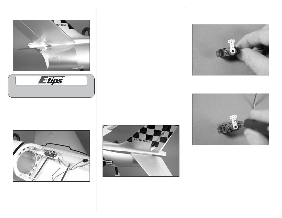
2. Use the radio system to center the rudder servo.
Note the direction of the servo arm in relationship
to the servo.
3. Use a pin vise and 1/16-inch (1.5mm) drill bit
to enlarge the hole in the servo arm as shown.