Motor and fan installation – E-flite F-15 Eagle DF ARF User Manual
Page 11
11
E-flite F-15 Eagle ARF Assembly Manual
Motor and Fan Installation
Required Parts
Impeller (2)
Impeller shaft (2)
Impeller shaft nut (2)
Fan housing (2)
Motor w/connectors(2)
Speed control w/connectors (2)
Fan cover
2mm x 8mm sheet metal screw (8)
18-inch extension
Y-harness
Servo (2)
2mm x 6mm machine screw (2)
2mm x 22mm sheet metal screw (2)
Required Tools and Adhesives
Hex wrench: 1.5mm
Phillips screwdriver: #1
Clear tape
Threadlock
Soldering iron
Solder
Hook and loop tape
String
Rotary tool with high speed grind bit and fine drum sander
Note: There is minimal airflow through the center of the
fuselage for ESC cooling. For this reason we have gone
to a larger amperage ESC than is really necessary. We
use the E-flite 40-amp ESC and have had no issues with
this setup in any of our test models.
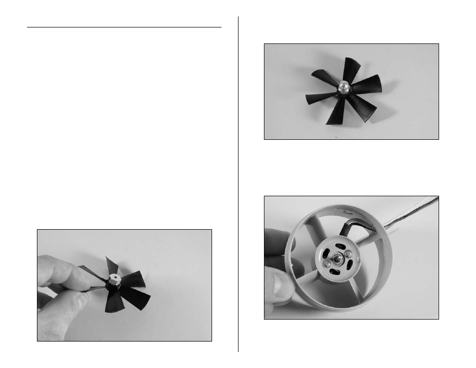
1. Slide the impeller shaft onto the impeller.
2. Use the impeller nut to secure the impeller shaft to
the impeller. Do not tighten at this time.
3. Use two 2mm x 6mm machine screws and a #1
Phillips screwdriver to secure the motor in the fan
housing. Route the motor leads to the outside of the
shroud as shown.
Note: You might have to grind a small hole in the shroud
to accommodate your motor leads.