Servo installation – E-flite Enticement F3P ARF User Manual
Page 15
15
E-flite Enticememt F3P Profile Assembly Manual
Servo Installation
Required Parts
Airframe assembly
Control horn support (3)
Rudder control horn support Heat-shrink tubing (4)
1/16 x 13/16-inch (2mm x 20mm) carbon control horn (4)
4-inch (103mm) carbon pushrods (2)
14
7
/
16
-inch (370mm) carbon pushrod (1)
15
5
/
8
-inch (398mm) carbon pushrod (1)
Plywood pushrod supports (4)
Required Tools and Adhesives
Foam-safe CA
Foam-safe CA activator
Low-temperature hot glue
Hot glue gun
Soldering iron
Hobby knife
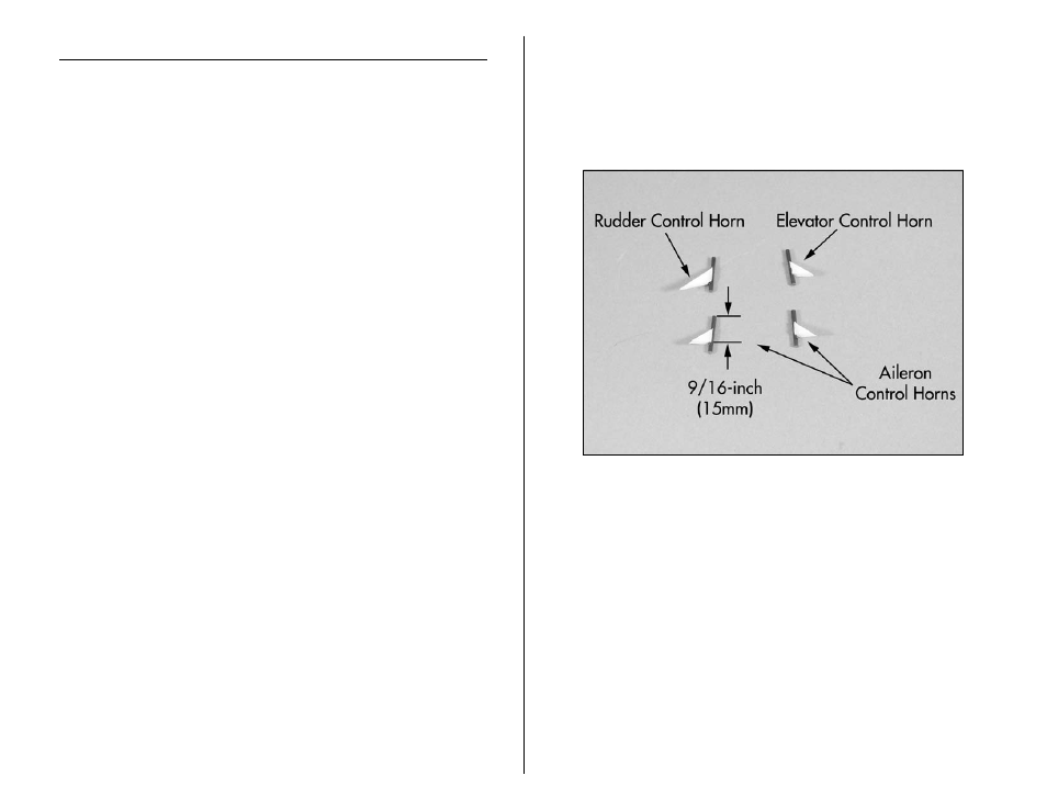
1. Use a ruler to measure 9/16-inch (15mm) on each
of the four 1/16 x 13/16-inch (2mm x 20mm) carbon
control horns. Use foam-safe CA to glue each of the
control horn supports to the rods with the bottom edge
of the support 9/16-inch (15mm) from the top of the
control horn.
Note: The rudder control horn support is longer than the
aileron and elevator supports. This longer edge faces
away from the control horn as shown in the photo.
- Habu 32x DF ARF (84 pages)
- A6M5 Zero 300 BNF Basic (17 pages)
- Hawker Sea Fury 480 ARF (28 pages)
- Mystique RES 2.9m ARF (52 pages)
- Super Cub 25e ARF (48 pages)
- AT-6 Texan 25 ARF (52 pages)
- LR-1A Pogo ARF 15e (21 pages)
- J-3 Cub 450 (40 pages)
- Hawker Hurricane 25e PNP (26 pages)
- Hawker Hurricane 25e PNP addendum (1 page)
- Apprentice 15e PNP (28 pages)
- Sukhoi SU-26m 480 ARF (28 pages)
- Beechcraft Bonanza 15e ARF (60 pages)
- Byp Yak 3D ARF (40 pages)
- Ultimate Fx 3D ARF (40 pages)
- Tribute FX 3D ARF (28 pages)
- Sobre 3D Profile (32 pages)
- Ascent EP Park Glider ARF (23 pages)
- Float Set Complete: Carbon-Z Cub (2 pages)
- Carbon-Z Cub PNP (27 pages)
- Carbon-Z Cub PNP Addendum (1 page)
- BAe Hawk 15 DF ARF (36 pages)
- Edge 540QQ 280 BNF Basic (19 pages)
- P-40 Warhawk 300 ARF (20 pages)
- Hawker Sea Fury 400 ARF (40 pages)
- Clipped Wing Cub 250 ARF (40 pages)
- T-34 Mentor 25e ARF (28 pages)
- Ultra Stick 25e ARF (40 pages)
- Ultra Stick 25e ARF Programming Guide (5 pages)
- Slick 3D 480 ARF (48 pages)
- PT-19 450 ARF (44 pages)
- Extra 330SC BP 3D ARF (40 pages)
- Cap 232 BP ARF (44 pages)
- Brio 10 ARF (56 pages)
- Park 480 BL Motor Combo (4 pages)
- Mini Edge 3D ARF (44 pages)
- Cessna 182 370 ARF (32 pages)
- Cessna 182/Park 400 BL Motor Combo (4 pages)
- Tribute 3D Profile ARF (40 pages)
- Fokker DVII 250 ARF (28 pages)
- Carbon-Z Yak 54 3X BNF Basic (23 pages)
- Carbon-Z Scimitar PNP (28 pages)
- UMX B-17G Flying Fortress BNF (18 pages)
- UMX Sbach 342 3D BNF Basic (17 pages)