Nose gear installation – E-flite T-34 Mentor 25e ARF User Manual
Page 9
9
E-flite T-34 Mentor 25e ARF Assembly Manual
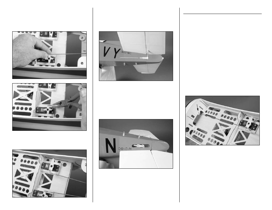
13. Slide a pushrod keeper on the wire from the
underside of the servo arm. Swing the connector
around and snap it on the pushrod wire to secure
the wire and servo horn. You may need to use
pliers to snap the keeper on the wire.
14. Repeat Steps 12 and 13 to install the 22
7
/
8
-
inch (581mm) rudder pushrod wire.
15. Slide a silicone keeper on the clevis and thread
the clevis on the elevator pushrod wire. With the
elevator servo centered, connect the clevis to the
nylon control horn. The elevator must align with the
stabilizer. If not, adjust the clevis so it does.
16. Slide a silicone keeper on the clevis and thread
the clevis on the rudder pushrod wire. With the
rudder servo centered, connect the clevis to the
nylon control horn. The rudder must align with the
fin. If not, adjust the clevis so it does. You may find
you need to remove the pushrod from the rudder
servo to make adjustments on the clevis.
Nose Gear Installation
Required Parts
Fuselage assembly Nylon steering arm
Nose gear assembly 3mm x 8mm socket head screw
Nose gear pushrod wire, 11
1
/
2
-inch (292mm)
3mm x 4mm machine screw
Radio system
Battery
Required Tools and Adhesives
Hex wrench or ball driver: 2.5mm
Phillips screwdriver: #1
Threadlock
1. Insert the 11
1
/
2
-inch (292mm) nose gear
pushrod wire in the slot near the nose gear mount
in the firewall. Guide the wire through the fuselage
formers and through the brass pushrod connector
as shown.