Motor and speed controller installation – E-flite T-34 Mentor 25e ARF User Manual
Page 11
11
E-flite T-34 Mentor 25e ARF Assembly Manual
Motor and Speed Controller Installation
Required Parts
Fuselage assembly Motor with hardware
Speed control
Hook and loop tape
Radio system
Battery
3mm x 15mm socket head screw (4)
Motor standoff, 3/8-inch (5mm)
Required Tools and Adhesives
Phillips screwdriver: #1
Threadlock
Hex wrench or ball driver: 2.5mm
Always use threadlock on metal-to-metal fasteners
to prevent them from vibrating loose.
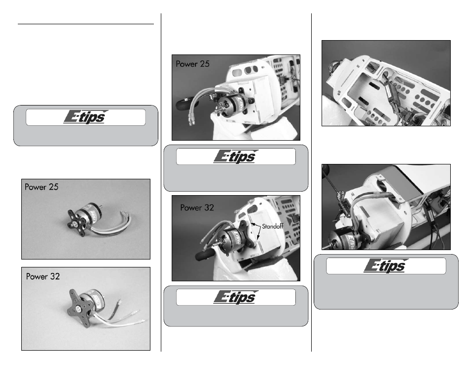
1. Attach the X-mount to the motor using the
screws provided with the motor and a #1 Phillips
screwdriver.
2. Attach the motor to the firewall using four 3mm
x 15mm socket head screws. Use a 2.5mm hex
wrench or ball driver to tighten the screws. Note
the different position of the mount in relationship to
the firewall for the Power 25 and Power 32.
When attaching the Power 32, you will need to
use the four 3/8-inch (5mm) standoffs between the
mount and firewall to set the correct motor spacing.
Always use threadlock on metal-to-metal fasteners
to prevent them from vibrating loose.
3. Insert the wires for the motor from the speed
control through the hole in the right-hand side of
the fuselage as shown.
4. The motor wires will exit the hole near the motor
box. Connect the wires from the motor to the wires
from the speed control.
If you use all E-flite components in the
power system, you can connect the ESC and
motor wires by matching the colors and the
motor will spin in the correct direction.