Cowling and spinner installation – E-flite T-34 Mentor 25e ARF User Manual
Page 12
12
E-flite T-34 Mentor 25e ARF Assembly Manual
5. Use hook and loop tape to secure the speed
control to the side of the fuselage.
6. Check the operation of your motor at this time
using the radio system. The motor should spin
counterclockwise when viewed from the front
of the fuselage. If not, follow the speed control
manufacturer’s recommendations to reverse the
direction if necessary.
Cowling and Spinner Installation
Required Parts
Fuselage assembly Cowling
3mm washer (4)
Propeller adapter
Propeller
Spinner cone
Spinner backplate
Motor battery
Hook and loop tape
Hook and loop strap (2)
3mm x 12mm self-tapping screw (2)
3mm x 12mm socket head screw (4)
Required Tools and Adhesives
Hex wrench or ball driver: 2.5mm
Phillips screwdriver: #1
Tapered reamer
Optional Items
12mm wrench
Aluminum spinner assembly
Hex wrench or ball driver: 3/32-inch
1. Use four 3mm x 12mm socket head screws
and four 3mm washers to attach the cowl to the
fuselage. Use a 2.5mm hex wrench or ball driver to
tighten the screws.
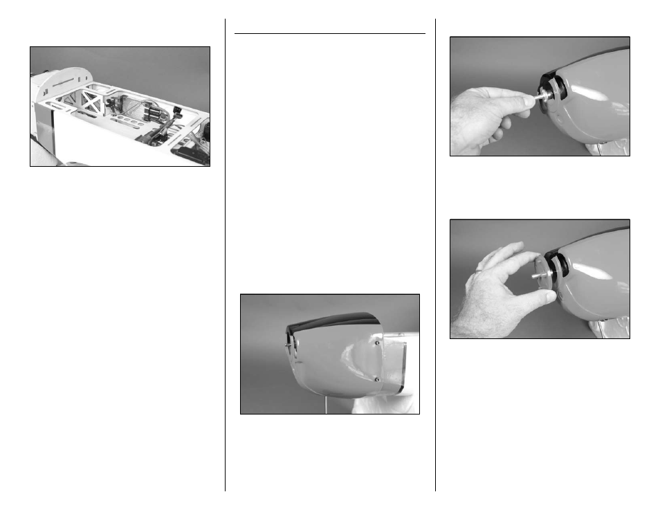
2. Slide the propeller adapter on the motor shaft.
3. Slide the spinner backplate on the propeller
adapter. It may be necessary to enlarge the hole in
the spinner backplate using a tapered reamer if it
does not fit on the propeller adapter.