Troubleshooting guide, Problem solution – Watts A2C-WB User Manual
Page 6
6
PROBLEM
SOLUTION
1. No water flow from either hot or cold water supply hose:
1. Plug IntelliFlow
®
into electrical outlet.
GREEN LED: OFF
2. Check electrical outlet for power (reset ground fault).
GREEN LED: ON
1. Plug washing machine into IntelliFlow
®
and turn on
YELLOW LED: OFF
washing machine.
RED LED: OFF / FAINT BLINK
2. Confirm operation of washing machine by plugging it into a
separate electrical outlet.
GREEN LED: ON
1. Leak sensor has detected water.
YELLOW LED: OFF
2. Check for broken or leaking hoses.
RED LED: ON
3. Unplug IntelliFlow
®
from electrical outlet, correct problem,
then re-insert plug into outlet to reset valve.
4. Turn on washing machine.
GREEN LED: ON
1. IntelliFlow
®
internal timing circuit has timed out.
YELLOW LED: OFF
Turn off washing machine to reset timing circuit.
RED LED: BLINKING
2. Turn on washing machine.
2. No water flow from one hose - (either Hot or Cold):
1. Service strainers on washing machine hoses.
GREEN LED: ON
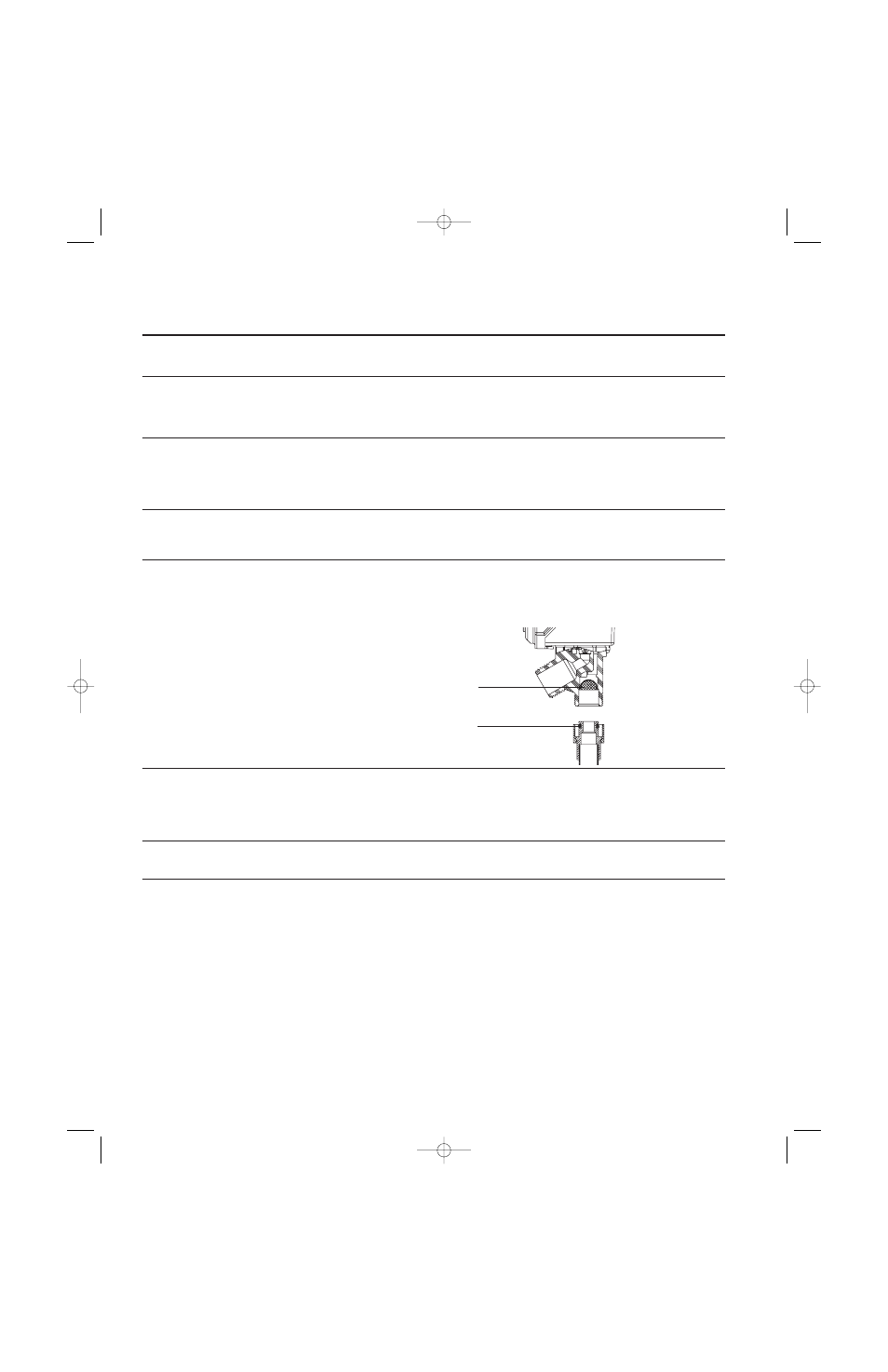
2. Service strainers on IntelliFlow
®
(see figure 1).
YELLOW LED: ON
Caution prior to servicing strainers, first remove power to
RED LED: OFF / FAINT BLINK
IntelliFlow
®
by unplugging, then shut off both hot and cold
water supply to IntelliFlow
®
.
3. Yellow LED Remains On
Some washing machine models include circuitry that causes a
GREEN LED: ON
slight current draw at all times. These models when connected
YELLOW LED: ON
to the IntelliFlow
®
can cause the water supply to be energized
RED LED: OFF / FAINT BLINK
continuously (Yellow LED: ON). The IntelliFlow
®
requires
calibration, see page 4 for calibration instructions.
4. Unit feels warm:
This condition is normal. Internal operating temperatures may
cause unit to feel warm to the touch.
5. Unit cycles ON/OFF:
Installation in a horizontal position can cause abnormal overheat-
ing of the unit which causes this cycling condition. Unit must be
installed in an upright position as shown on pages 2 and 3.
Troubleshooting Guide
Strainer
O-Ring
Figure 1
IS-A2C-M1-A2C-WB-M1.qxd 6/22/09 2:30 PM Page 6