Principles of operation, Installation, Operation – Watts 2300 User Manual
Page 2: Troubleshooting, Erratic operation, Dismantling, Valve setting
Installation and Maintenance Instructions
(Brackets refer to item number)
Principles of Operation
When the water supply is cut in, the valve is in wide open posi-
tion. Water flowing to the system creates a rising delivery pres-
sure which feeds back through the control ports to the underside
of diaphragm (8). As the pressure on diaphragm (8) approaches
a balance with the force exerted by adjusting spring (5), disc (20)
is throttled to a position where just enough water flows to main-
tain the set delivery pressure.
Installation
Carefully clear inlet piping system of foreign matter and mount
regulator with the flow arrow pointing in the direction of flow.
Preferred position for 2300 valves is in a horizontal line with
spring chamber up. When so mounted, the tendency of sedi-
ment to settle in the control ports is practically eliminated.
Provide a three-valve bypass to facilitate inspection of the reduc-
ing valve without interrupting service. Avoid damaging effects of
foreign matter in the flow by using a strainer ahead of the valve.
This valve should be installed where it is accessible with sufficient
clearance for cleaning, service or adjustment.
Operation
On starting up, proceed as follows:
1. Open the inlet stop valve gradually until the reducing valve
takes control as indicated by the delivery pressure gage.
2. Turn adjusting screw (1) clockwise to increase the delivery
pressure, counterclockwise to lower it.
CAUTION: Any time a reducing valve is adjusted, the use of a
pressure gauge is recommended to verify correct pressure set-
ting. Do not bottom out adjusting screw on spring chamber.
Troubleshooting
Inadequate flow or delivery pressure:
1. Check initial pressure to see if full intended line pressure is
applied at the valve inlet.
Reduced pressure builds up:
1. Foreign matter may be lodged between disc (20) and seat ring
(19). Remove blind flange (24) to inspect.
2. Diaphragm (8) may be ruptured. Remove spring chamber (4)
to inspect.
3. Sealing ring (16) may be damaged. See dismantling
instructions below to replace.
Erratic Operation
Complete dismantling is recommended.
1. Check for clogged control ports connecting body outlet with
diaphragm chamber.
2. Check for deposits causing sticking of sealing ring (16) or stem
(14) in their respective guides.
Dismantling
To change or inspect composition disc or sealing ring:
1. Remove blind flange (24).
2. Remove stem nuts (22). Keep stem from turning by inserting
screw driver in slot on end of stem.
3. Disc holder (21) will drop out. Carefully remove balance pis-
ton (18) so as not to damage sealing ring (16) as it is pulled
through seat ring (19).
To examine diaphragm or stem:
1. Remove compression from spring by turning adjusting
screw (1) counterclockwise.
2. Remove diaphragm bolts (9) and lift off spring chamber
(4).
3. Lift pressure plate (7) to withdraw diaphragm and stem
from valve.
4. To examine diaphragm, disassemble coupling nut (6) and
lift off pressure plate (7).
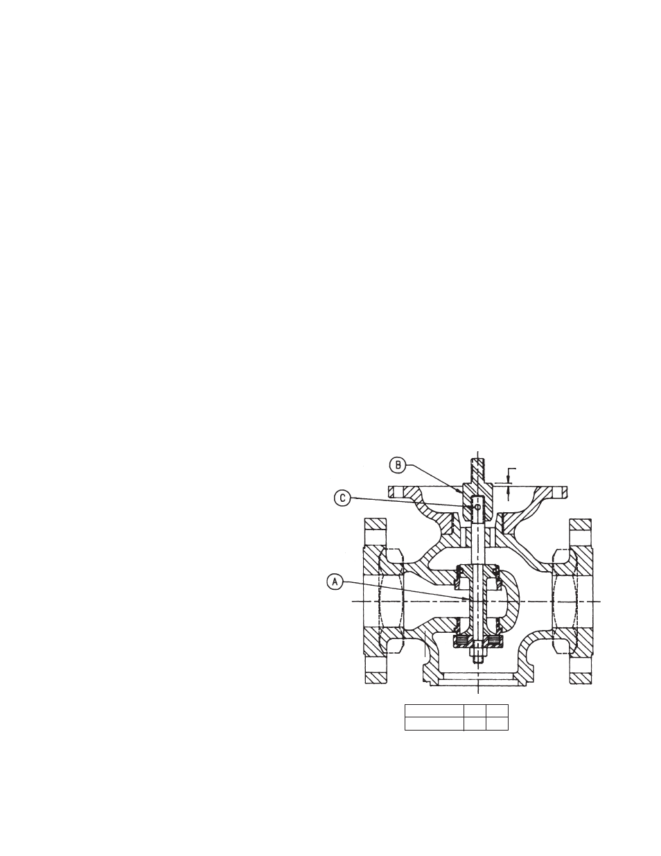
Valve Setting
Should the threaded connection between stem coupling
(11) and stem (14) be disturbed, proceed as follows:
1. Insert stem assembly (A) and hold disc on seat ring in
closed position, as shown.
2. Screw stem coupling (B) on stem until travel setting T is
reached.
3. Remove stem assembly (A) and lock setting by drilling
hole drilling hole and inserting dowel pin (C).
NOTE: Annual inspection of the rubber components
and control parts is recommended to ensure proper
operation.
Valve Size
3 4
Dimension T
3
⁄
16
17
⁄
64
DIMENSION ‘T’