Watts LFF127W User Manual
Lead free, High capacity water pressure reducing valves, For commercial and industrial applications
Model LF127W and
LFF127W
High Capacity Water Pressure
Reducing Valves
Size: 3" - 4"
Model LF127W and LFF127W High Capacity Water Pressure
Reducing Valves are designed to reduce incoming water pres-
sure to a sensible level to protect plumbing system components
and reduce water consumption. The LF127W and LFF127W are
remote control type regulators ideal for commercial and industrial
applications where a regulator must reach full capacity with a
minor drop in reduced pressure. These models are also suit-
able for applications where close pressure regulation is required
through extensive volume demand. These models are suitable
for water supply pressures up to 175psi (12.1 bar) and may be
adjusted from 25 – 100psi (172 – 690 kPa). All parts are quickly
and easily serviceable.
The LF127W and LFF127W feature Lead Free* construction to
comply with Lead Free* installation requirements.
Features
• Lead Free* body construction
• Replaceable stainless steel seat
• Outstanding maintenance features
• Close control of reduced pressure
• High temperature-resisting diaphragm
• Interchangeable diaphragm chamber
Specifications
A Water Pressure Reducing Valve shall be installed on the water
service pipe near its entrance to the building where supply
main pressure exceeds 60psi (413 kPa) to reduce it to 60psi
(413 kPa) or lower. The water pressure reducing valve shall be
constructed using Lead Free* materials. Lead Free* regulators
shall comply with state codes and standards, where applicable,
requiring reduced lead content. The valve shall be equipped with
a
3
⁄
8
" tapping to receive equalizer piping and a
3
⁄
4
" tapping to
receive auxiliary regulator piping for low flow requirements. Valve
shall be a Watts Model LF127W or LFF127W.
* The wetted surface of this product contacted by consumable
water contains less than 0.25% of lead by weight.
Materials
For Commercial and Industrial Applications
ES-LF127W
Job Name –––––––––––––––––––––––––––––––––––––––––––
Contractor ––––––––––––––––––––––––––––––––––––––––––––
Job Location –––––––––––––––––––––––––––––––––––––––––
Approval –––––––––––––––––––––––––––––––––––––––––––––
Engineer –––––––––––––––––––––––––––––––––––––––––––––
Contractor’s P.O. No. ––––––––––––––––––––––––––––––––––
Approval –––––––––––––––––––––––––––––––––––––––––––––
Representative ––––––––––––––––––––––––––––––––––––––––
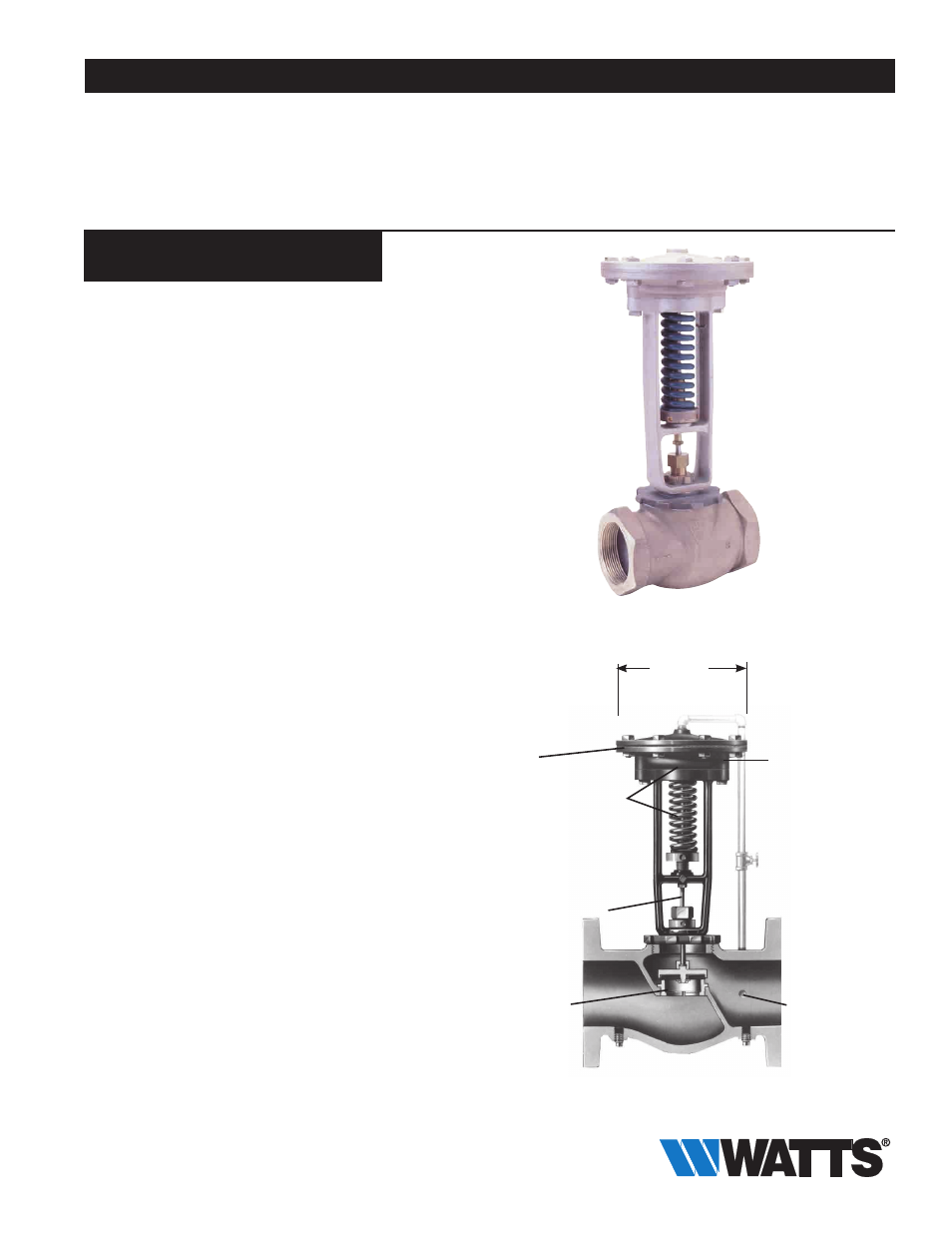
3" (80mm) LF127W
Watts product specifications in U.S. customary units and metric are approximate and are provided for reference only. For precise measurements,
please contact Watts Technical Service. Watts reserves the right to change or modify product design, construction, specifications, or materials with-
out prior notice and without incurring any obligation to make such changes and modifications on Watts products previously or subsequently sold.
LEAD FREE
*
6", 8" or 10"
(150, 178, or 200mm)
depending upon reduced
pressure range.
Diaphragm chamber
is easily changed by
the removal of
two cap screws.
High
temperature-resisting
diaphragm.
Requirements of various
pressure conditions can
be quickly met by
interchanging the various
sizes of diaphragm cham-
bers - 6", 8", 10"
(150, 178, 200mm)
as well as by interchanging
spring.
Stainless steel stem.
Replaceable
stainless
steel seat.
Tapping provided in
low pressure side of
body for 4" valve to
permit convenient,
economical attachment
of equalizer line.