Configuration – Banner PVD100 Pallet Sensor User Manual
Page 4
Configuration
To configure the PVD, set the DIP switches as shown, using the supplied plastic screwdriver to avoid damaging the switches or causing a
short circuit.
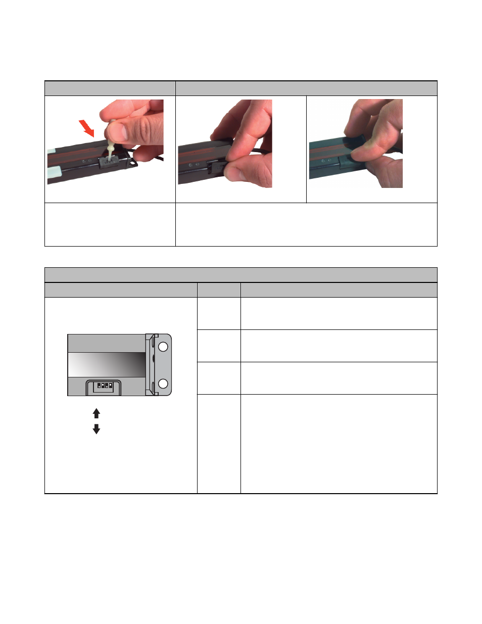
Cover Removal
Cover Replacement
Insert a fingernail or small screwdriver into
the slot; apply gentle pressure, angling
away from the sensor lens. The cover will
remain tethered to the sensor housing.
To replace the switch cover, align one edge of the cover with the edge of the sensor
housing opening. Then press the front corners into place.
The switches determine four status operating modes:
PVD Configuration DIP Switch Settings
The factory default setting is ON for all switches
Switch
Condition
1 2 3 4
O
F
F
O
N
ON
OFF
Example Shown:
Switch #1
OFF
Switch #2
ON
Switch #3
OFF
Switch #4
ON
Figure 6. Configuration DIP switch setting posi-
tions
1
ON = PNP output
OFF = NPN output
2
ON = Normally Open
OFF = Normally Closed
3
ON = Job light steady
OFF = Job light flashes
4
Job light control input: Connect the white wire as follows:
PNP Output
ON = Job light ON for +10 to 30V dc (29kΩ input impedance)
OFF = Job light ON for 0 to 1.5V dc/open circuit
NPN Output
ON = Job light ON for +10 to 30V dc/open circuit
OFF = Job light ON for 0 to 1.5V dc (10kΩ input impedance)
PVD Series Parts Verification Sensor
4
www.bannerengineering.com - tel: 763-544-3164
P/N 113230_web
Rev. E