Installation, Figure 1. sensor features – Banner PVD100 Pallet Sensor User Manual
Page 2
The DIP-switch-selectable PNP/NPN output interfaces to a system controller, which is pre-programmed for a specific sequence of tasks.
Mounted with its visible red beams stretching across each parts bin, the sensor job light signals the assembler which bins contain items
to be picked in a given operation and in what order they should be picked.
As the assembler takes a part in sequence and breaks the beam, the sensor senses that the part was removed and it sends an output
signal to the controller. The controller then verifies if the correct part was taken and may respond by turning that job light OFF, activating
the job light of the next bin in the sequence. If the assembler reaches into a bin out of sequence, the PVD turns on its output to signal the
system controller and turns on its red job light to signal the assembler that an incorrect pick has occurred.
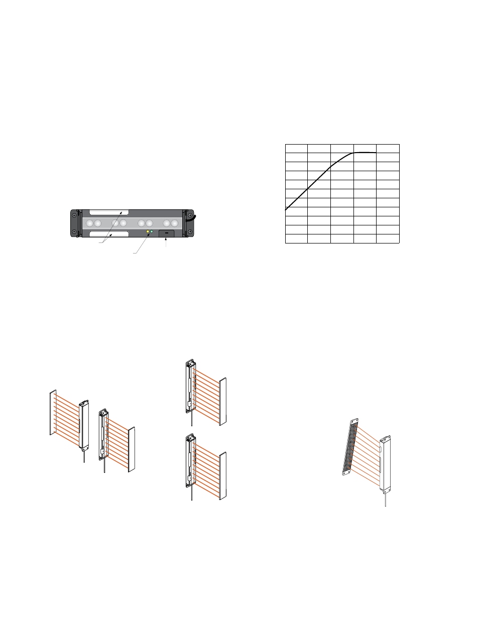
Standard configuration options are selected by means of a bank of four DIP switches behind a press-on black rubber cover. DIP switch
options include: PNP or NPN output, Normally Open or Normally Closed operation, steady or flashing job light, and job light control input.
MODE
Status
Indicators
Configuration
Switch Cover
Job Lights
(Error Lights)
Figure 1. Sensor features
0
0
10 mm
20 mm
30 mm
40 mm
50 mm
60 mm
70 mm
80 mm
90 mm
100 mm
110 mm
2.5 m
2 m
1.5 m
1 m
0.5 m
Range
Minimum Object Size
to Always Block a Beam
Figure 2. Minimum object detection size (retroreflective operation)
Installation
Multiple sensors located farther than the sensor's maximum range from one another are unlikely to cause crosstalk problems. However,
when multiple sensors are mounted in a confined area, take care to avoid crosstalk between them. Alternate the relative position of
adjacent sensors and/or reflectors. Sensors positioned above or below one another should not create crosstalk difficulties. Mount the
sensor and reflector parallel.
Sensor
Reflector
Reflector
Sensor
MODE
MODE
Sensor
Sensor
Reflector
Reflector
MODE
Figure 3. Examples of Appropriate Positions
Figure 4. Example of Incorrect Position
PVD Series Parts Verification Sensor
2
www.bannerengineering.com - tel: 763-544-3164
P/N 113230_web
Rev. E