Mounting, Hookups – Banner PVD100 Pallet Sensor User Manual
Page 3
Mounting
The wide beam pattern of PVD sensors simplifies their alignment. M4 stainless steel fasteners
and two stainless steel brackets are included with each sensor.
Mount the sensor and its reflector, if used, parallel to one another in the same plane, and their
tops and bottoms aligned.
1. From a common point of reference, make measurements to locate the sensor and its reflec-
tor, if used, in the same plane with their midpoints directly opposite each other.
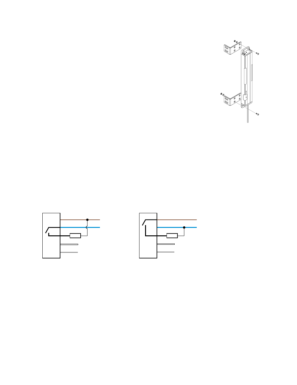
2. Mount the included brackets to the top and bottom of each sensor, as shown.
3. Mount the sensor in its brackets and the reflector, if used, being careful to position the sen-
sor's red lenses directly facing the reflector.
4. Measure from one or more reference planes (for example, the building or bin floor) to the
same point(s) on the emitter and receiver to verify their mechanical alignment. (If the sen-
sors/reflectors are mounted exactly vertical or horizontal, a carpenter’s level may be helpful.
A straightedge or a string extended between the sensor and the bin wall may also be help-
ful.)
5. Also check “by eye” for line-of-sight alignment.
6. Make any necessary final mechanical adjustments, and hand-tighten the bracket hardware.
7. After the electrical hookup is complete, check for beam alignment. If necessary, re-align the
emitter and receiver at that time.
M
O
D
E
Figure 5. PVD Mounting Hard-
ware
Hookups
All models feature integral 2 m (6.5 ft) long, 3.3 mm (0.13 inch) dia. PVC-jacketed cables. Models whose model numbers end in “Q” are
terminated with quick-disconnect (QD) Euro-style 5-pin connectors; other models have unterminated ends. Optional mating QD cables
are available. Either 4-pin or 5-pin QD cables may be used; the center pin of a 5-pin cable (gray wire, pin 5) is unused in normal opera-
tion.
Wiring is functionally identical for cabled and quick-disconnect models.
NPN (Sinking) Output
PNP (Sourcing) Output
Key
Job Light Control
Not Used
2
5
12-30V dc
–
+
1
3
4
Load
12-30V dc
Job Light Control
Not Used
–
+
1
3
2
4
5
Load
1 = Brown
2 = White
3 = Blue
4 = Black
5 = Gray
See
on page 4 for job light control input requirements.
PVD Series Parts Verification Sensor
P/N 113230_web
Rev. E
www.bannerengineering.com - tel: 763-544-3164
3