Push button lockout, Self-diagnostic error modes, Gate input – Banner D10 Expert with Numeric Display—Discrete User Manual
Page 15: Specifications
Push Button Lockout
• Prevents unwanted adjustments or tampering of the push buttons
• Push buttons can be enabled or disabled only from the remote line and only during normal RUN mode
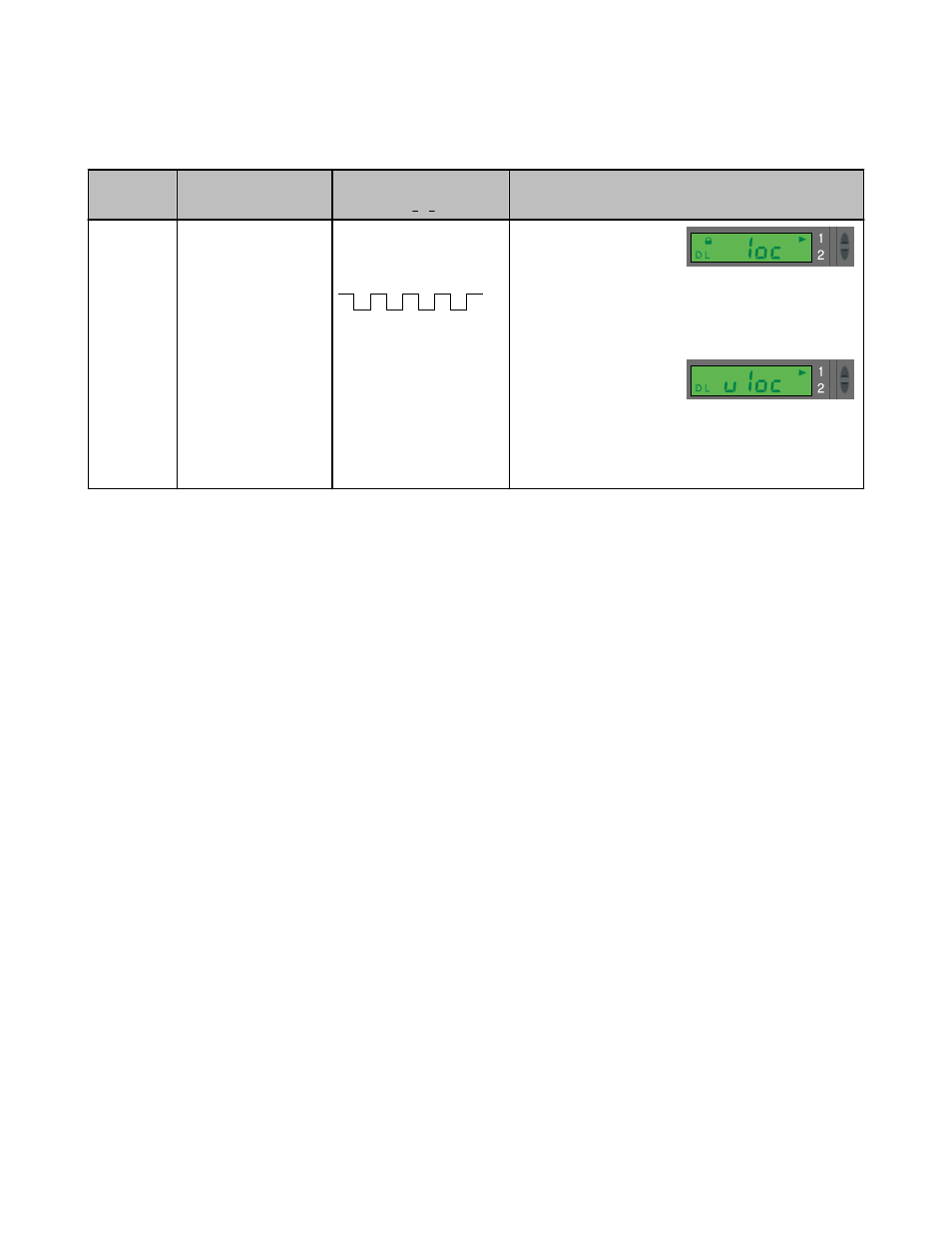
Push Button
Remote
0.04 seconds < T < 0.8 seconds
Result
Enable or
Disable
Push But-
tons
Not available with push-
button programming.
From RUN mode, quad-
pulse the remote line to tog-
gle between selections.
T
T
T
T
T
T
T
Push buttons Disabled
• Display flashes "loc"
• Padlock icon appears
• Sensor remains in RUN
mode
Push Buttons Enabled
• Display flashes "uloc"
• Padlock icon disap-
pears
• Sensor remains in RUN
mode
Self-Diagnostic Error Modes
In the unlikely event that the setup parameters are lost or become corrupt, the display will continuously scroll: “USEr PSF Error.” Reteach
the sensor to recover. If the problem persists, contact your Banner representative for further information.
Gate Input
The pink wire is configured as a gate input. When this wire is pulled low (i.e., to the sensor ground; 0-0.5V dc), it inhibits the outputs from
switching, while all other sensor functions continue to be enabled. This feature is useful for controlling when the outputs are allowed to
change states. Gate input function response time is 1 millisecond.
Specifications
Required Fiber-Optic Cable
Banner P-Series plastic fibers
Sensing Beam
680 nm visible red or 525 nm visible green, depending
on model
Supply Voltage and Current
4-20 mA Analog Models: 12 to 24V dc (10% maxi-
mum ripple) at less than 65 mA, exclusive of load
0-10V dc Analog Models: 15 to 24V dc (10% maxi-
mum ripple) at less than 70 mA, exclusive of load
Supply Protection Circuitry
Protected against reverse polarity and transient voltage
Output Configuration
2 independently configurable outputs, depending
on model: NPN w/analog (4-20 mA or 0-10V) or PNP
w/analog (4-20 mA or 0-10V)
Adjustments
Push-button or remote programming of response time,
OFF-delay, light/dark operate, and display
Indicators
Four-digit digital display plus LED indicators for active
channel, push-button lockout, OFF-delay and light/dark
operate selection; 2 yellow output indicators
Construction
Black ABS/polycarbonate alloy (UL94 V-0 rated) hous-
ing, clear polycarbonate cover
Environmental Rating
IEC IP50, NEMA 1
Connections
PVC-jacketed 2 m or 9 m (6.5' or 30') 6-wire integral
cable or integral 6-pin Pico-style quick-disconnect
D10 Expert™ - Analog and Discrete Outputs
P/N 65448_web
rev. F
www.bannerengineering.com - tel: 763-544-3164
15