Step 7: install your surecross ® radios, Dx70, dx80, and performance mounting template – Banner SureCross DX80 Wireless Networks User Manual
Page 2
Banner Engineering Corp., 9714 Tenth Ave. No., Minneapolis, MN USA 55441 • Phone: 763.544.3164 • www.bannerengineering.com • Email: [email protected]
Step 7: Install Your SureCross® Radios
For most outdoor applications, we recommend installing your SureCross devices inside a secondary
enclosure. If not using an enclosure, mount the DX80 where rain or snow will drain away from the unit.
To minimize the damaging effects of ultra-violet radiation, avoid mounting the Gateway or Node facing
intense direct sunlight.
For additional information, including installation and setup, weatherproofing, device menu maps, troubleshooting, and a list of accessories, please refer to
the SureCross™ DX80 Wireless I/O Network product manual, Banner p/n
132607
.
The manufacturer does not take responsibility for the violation of any warning listed in this
document.
CAUTION. Make no modifications to this product. Any modifications to this product not
expressly approved by Banner Engineering could void the user’s authority to operate the
product. Contact the Factory for more information.
Lightning Arrestors/Surge Protection. Always use lightning arrestors/surge protection with all
remote antenna systems to avoid invalidating the Banner Engineering Corp. warranty. No surge
protector can absorb all lightning strikes. Do not touch the SureCross device or any equipment
connected to the SureCross device during a thunderstorm.
All specifications published in this document are subject to change. Banner reserves the right
to modify the specifications of products, prior to their order, without notice. Banner Engineering
reserves the right to update or change documentation at any time. For the most recent version
of any documentation, please refer to our website: www.bannerengineering.com. © 2009-2012
Banner Engineering Corp. All rights reserved.
Banner Engineering Corp. warrants its products to be free from defects in material and workmanship for one year following the date of shipment. Banner Engineering Corp. will repair or replace, free of
charge, any product of its manufacture which, at the time it is returned to the factory, is found to have been defective during the warranty period. This warranty does not cover damage or liability for
misuse, abuse, or the improper application of the Banner product.
THIS LIMITED WARRANTY IS EXCLUSIVE AND IN LIEU OF ALL OTHER WARRANTIES WHETHER EXPRESS OR IMPLIED (INCLUDING, WITHOUT LIMITATION, ANY WARRANTY OF
MERCHANTABILITY OR FITNESS FOR A PARTICULAR PURPOSE), AND WHETHER ARISING UNDER COURSE OF PERFORMANCE, COURSE OF DEALING OR TRADE USAGE.
This Warranty is exclusive and limited to repair or, at the discretion of Banner Engineering Corp., replacement. IN NO EVENT SHALL BANNER ENGINEERING CORP. BE LIABLE TO BUYER OR ANY
OTHER PERSON OR ENTITY FOR ANY EXTRA COSTS, EXPENSES, LOSSES, LOSS OF PROFITS, OR ANY INCIDENTAL, CONSEQUENTIAL OR SPECIAL DAMAGES RESULTING FROM ANY PRODUCT
DEFECT OR FROM THE USE OR INABILITY TO USE THE PRODUCT, WHETHER ARISING IN CONTRACT OR WARRANTY, STATUTE, TORT, STRICT LIABILITY, NEGLIGENCE, OR OTHERWISE.
Banner Engineering Corp. reserves the right to change, modify or improve the design of the product without assuming any obligations or liabilities relating to any product previously manufactured by
Banner Engineering Corp.
Step 6: Conduct a Site Survey Using the Menu System
A site survey analyzes the radio communications link between the Gateway and a selected Node and reports the number of missed packets that required
a retry.
Use the Gateway to initiate a site survey analysis.
1. Remove the rotary dial access cover.
2. Set the Gateway’s rotary dials to the Node address you want to survey. For example, to analyze Node 1’s signal, change the Gateway’s left
rotary dial to 0 and its right rotary dial to 1. (To analyze Node 12’s signal, change the Gateway’s left rotary dial to 1 and its right rotary dial to
2.)
3. Single-click button 1 to scroll across the menu levels until reaching the Site Survey (SITE) menu.
4. Single-click button 2 to enter the Site Survey menu.
5. Single-click button 2 to begin conducting a Site Survey with the selected Node.
The Gateway counts the data packets received from the Node.
6. Examine reception readings (M, R, Y, G). M displays the percent of missed packets while R, Y, and G display the percentage of received packets
at a given signal strengths: R = RED marginal signal; Y = YELLOW good signal; G = GREEN excellent signal
7. To end the Site Survey, double-click button 2.
8. Change the Gateway's right rotary dial back to 0.
9. Double-click button 2 to move back to the top level menu.
10. Single-click button 1 to return to RUN mode.
11. Install the rotary dial access cover, referring to the Installation section of the manual to create an IP67 seal.
65 mm
[2.56”]
65 mm
[2.56”]
User Configuration Tool (UCT)
The User Configuration Tool (UCT) offers an easy way to link
I/O points in your wireless network, view I/O register values
graphically, and set system communication parameters when
a host system is not part of the wireless network.
The User Configuration Tool
requires the USB to RS-485
converter cable, BWA-
UCT-900.
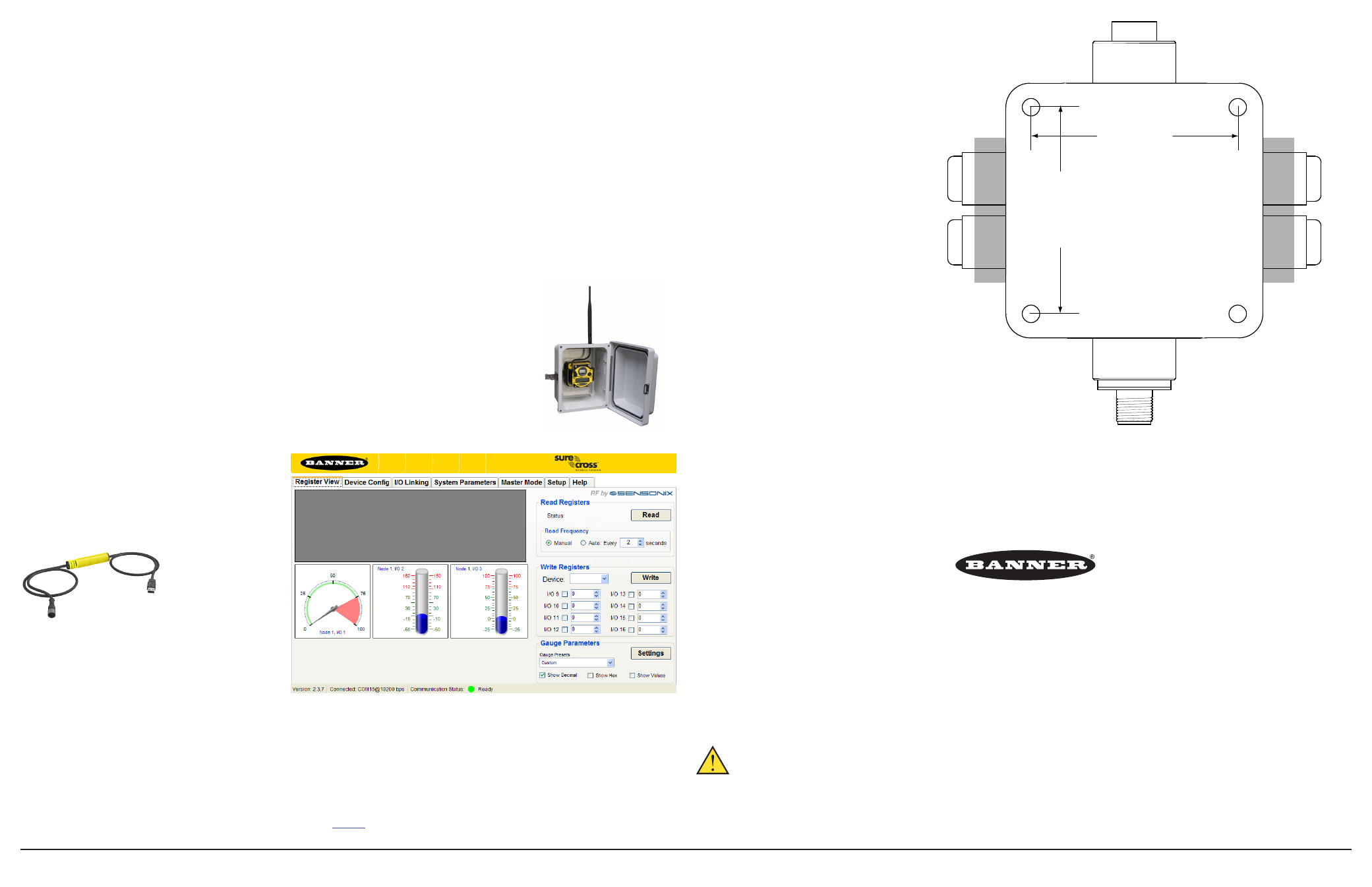
DX70, DX80, and Performance Mounting Template
The gray-shaded section represents the
DX80...C housings’ removable terminal headers.
Only if you are using the printed copy provided
by Banner can this be used as a mounting
template.