Configuration, M-gage node dip switches – Banner SureCross DX80 Wireless M-GAGE Node User Manual
Page 5
P/N 131598 rev. F
5
Banner Engineering Corp. • Minneapolis, MN U.S.A
www.bannerengineering.com • Tel: 763.544.3164
SureCross™ DX80 M-GAGE™ Node with Integrated Battery
Configuration
There are four ways to configure an M-GAGE™ Node:
M-GAGE Node DIP switches
1.
M-GAGE Gateway DIP switches (see Banner document p/n 139075 for more information)
2.
M-GAGE configuration using the M-GAGE Node register 13
3.
Modbus registers 7, 15, and 16 to send Modbus configuration commands (see Banner document p/n 132114 for more information)
4.
M-GAGE Node DIP Switches
The DIP switches on the M-GAGE board change the configuration of the device. After making any changes to the DIP switches, cycle power to
the device to activate the changes.
In Rotary Switch address mode, the left rotary dial establishes the network ID and the right rotary dial sets the device ID. The wireless
network is restricted to a maximum of 16 devices. Extended addressing mode allows for specific Node to Gateway binding and allows network
expansion for more than 16 devices in a wireless network. For most users, this switch is OFF. For more information on extended address
mode, refer to the SureCross™ Wireless I/O Network product manual, p/n 132607. Because the M-GAGE has no LCD, triple-click button 2 to
activate binding mode instead of using the menu structure listed in document 132607.
Setting the Node’s Use Switch Settings DIP switch (DIP switch 2) to the ON position allows the Node DIP switches 3 through 8 to be used for
configuration. Configuration settings from the M-GAGE Gateway’s DIP switches are active regardless of the Node’s Use Switch Settings DIP
switch position.
Set the Node’s Use Switch Settings DIP switch to the OFF position to use either the Web Configuration tool to set the parameters or to send
commands to I/O 13 directly from the host system.
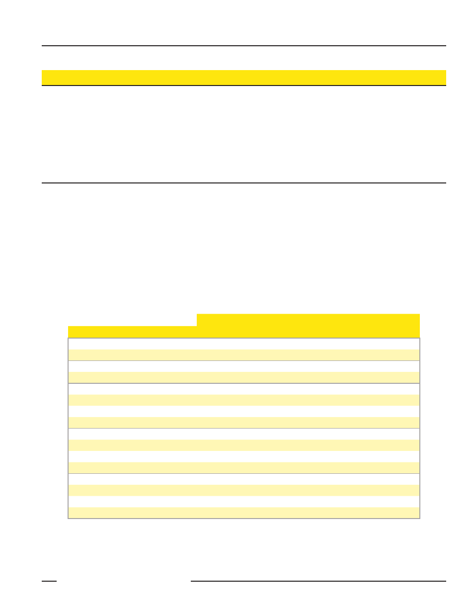
Switches
Device Settings
1
2
3
4
5
6
7
8
Rotary Switch Address Mode
OFF*
Extended Address Mode
ON
Use Configuration
OFF*
Use Switch Settings
ON
Low Pass Filter T2
OFF*
OFF*
Low Pass Filter T3
OFF
ON
Low Pass Filter T0
ON
OFF
Low Pass Filter T1
ON
ON
Sample High Count 4
OFF*
OFF*
Sample High Count 8
OFF
ON
Sample High Count 1
ON
OFF
Sample High Count 2
ON
ON
Sample 250 milliseconds
OFF*
OFF*
Sample 500 milliseconds
OFF
ON
Sample 1 second
ON
OFF
Sample 125 milliseconds
ON
ON
* Default configuration