Modbus register block baseline – Banner SureCross DX80 Wireless M-GAGE Node User Manual
Page 3
P/N 131598 rev. F
3
Banner Engineering Corp. • Minneapolis, MN U.S.A
www.bannerengineering.com • Tel: 763.544.3164
SureCross™ DX80 M-GAGE™ Node with Integrated Battery
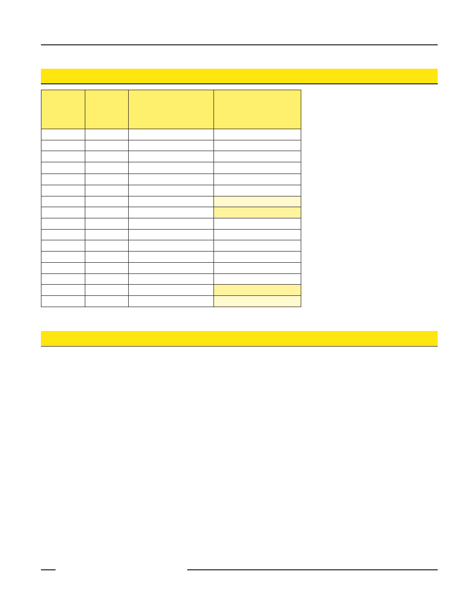
There are sixteen Modbus holding registers
for each device. Calculate the holding
register number for each device using the
equation:
Register number = I/O# + (Node# • 16).
Because the Gateway is always device 0, the
Gateway’s holding registers are registers 1
through 16 while registers for Node 1 are 17
through 32.
Using the equation, the register number for
I/O point 15 for Node 7 is 127.
The M-GAGE value in I/O 1 is the deviation
between the total measured magnetic field in
the X, Y, and Z axes and the stored baseline.
To send configuration messages, use the
Node’s I/O point 13.
To create a baseline command, use a control
message or use the Node’s I/O point 14.
For more instructions, refer to the Baseline
section.
I/O
Point
Gateway
Modbus
Holding
Register
Node
Modbus
Register
DX80
M-GAGE™ FLEX(Node)
1
1
1 + (Node# × 16)
M-GAGE
2
2
2 + (Node# × 16)
3
3
3 + (Node# × 16)
4
4
4 + (Node# × 16)
5
5
5 + (Node# × 16)
6
6
6 + (Node# × 16)
7
7
7 + (Node# × 16)
Reserved
8
8
8 + (Node# × 16)
Device Message
9
9
9 + (Node# × 16)
10
10
10 + (Node# × 16)
11
11
11 + (Node# × 16)
12
12
12 + (Node# × 16)
13
13
13 + (Node# × 16)
Configuration Message
14
14
14 + (Node# × 16)
Baseline Command
15
15
15 + (Node# × 16)
Control Message
16
16
16 + (Node# × 16)
Reserved
Modbus Register Block
Baseline
The baseline function of the M-GAGE Node stores the ambient magnetic field values of the X, Y, and Z axes as a baseline reading. Once this
baseline is established, any deviation in the magnetic field will be reflected in the M-GAGE register. The more disruption in the magnetic field,
the larger the M-GAGE register value.
For a host-connected system using standard Gateways, set the baseline magnetic field by writing to a Modbus register. Sending the value of
4096 (0x1000) to the Node’s I/O point 15 (Control Message) triggers the M-GAGE to read the existing magnetic field as the new baseline.
For non-host connected systems, use one of the two special M-GAGE Gateways to set the baseline:
The inputs of the DIP switch M-GAGE Gateway (model DX80G*M6*6P6ZP) are mapped to the M-GAGE Node’s I/O point 14. Activating
•
the Gateway’s input for at least five seconds triggers the M-GAGE to use the existing magnetic field as the new baseline.
The special M-GAGE Gateway (model DX80G*M6*6P6Z) uses special mapping to baseline up to six M-GAGE Nodes.
•