Buried installation – Banner SureCross DX80 Wireless M-GAGE Node User Manual
Page 10
Banner Engineering Corp. • Minneapolis, MN U.S.A
www.bannerengineering.com • Tel: 763.544.3164
10
P/N 131598 rev. F
SureCross™ DX80 M-GAGE™ Node with Integrated Battery
Buried Installation
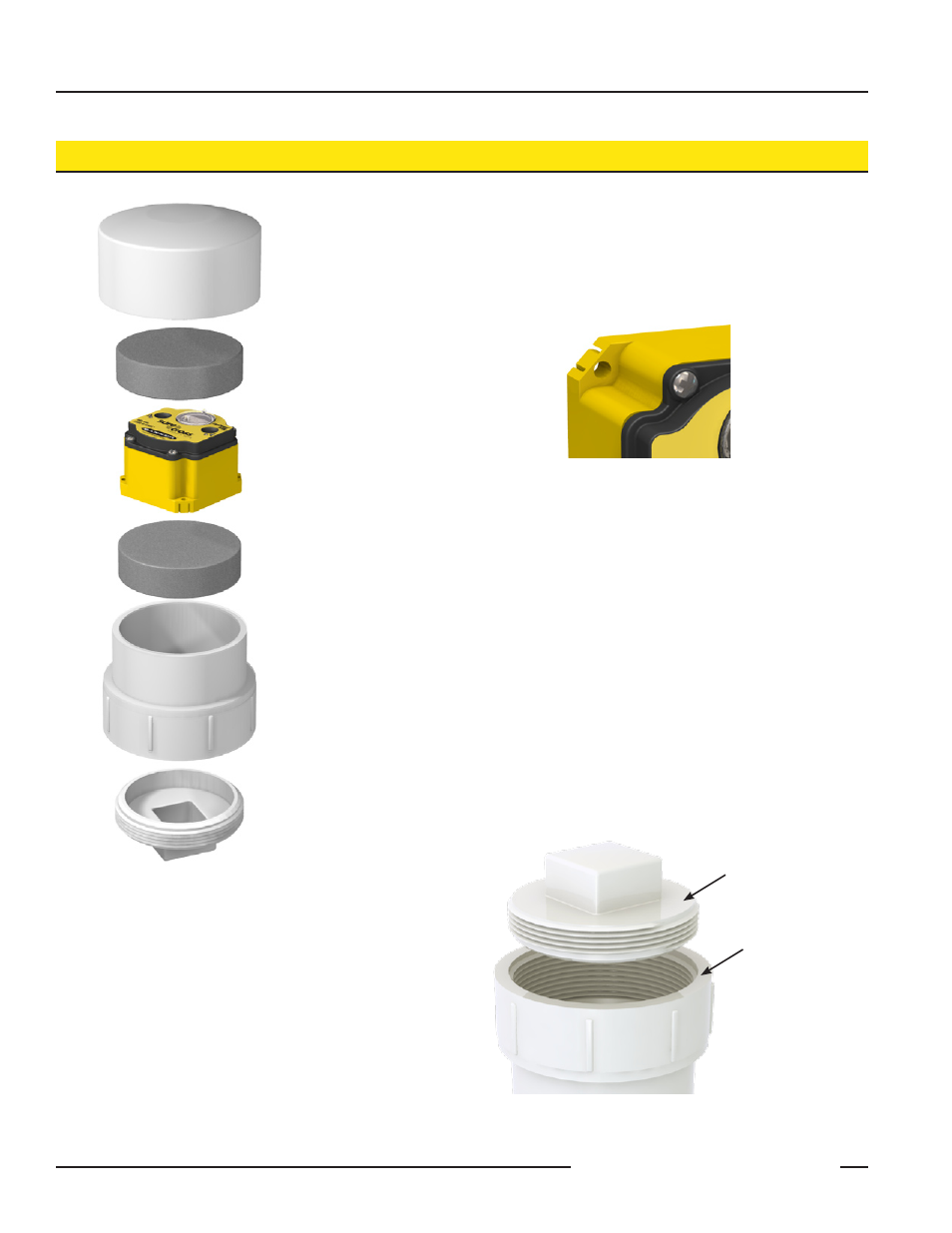
To protect the M-GAGE in a buried application, Banner Engineering recommends
installing the device within a protective 4” dia PVC enclosure. Form the enclosure
using a cleanout fitting with a thread-out plug and end cap.
To create a waterproof environment for the M-GAGE Node, follow these steps:
1. Cut part of the mounting ears off, as shown in figure 5, to allow the
M-GAGE Node to fit through the cleanout fitting.
Cleanout thread-out
plug, 4” dia PVC
Cleanout fitting, 4” dia
PVC
End cap, 4” dia PVC
Figure 4. Additional items needed but not
shown: 1/2” wide PTFE seal tape, PVC primer,
PVC cement
1 1/4 thick foam
1 1/4 thick foam
2. Coat the joint area between the end cap and cleanout fitting with PVC
primer and PVC cement.
3. Insert the cleanout fitting into the end cap until the fitting comes into full
contact with the end cap.
4. Allow the adhesive to dry for 24 hours.
5. Wrap several layers of PTFE seal tape around the entire threaded edge
of the cleanout plug.
6. Insert a 1” to 1 1/2” thick piece of foam into the end cap.
7. Enable the M-GAGE Node by pressing button 1 for four seconds. LED
1 should flash green to indicate the device is powered up and operat-
ing.
8. Insert the M-GAGE Node into the capsule on top of the first foam piece
as shown in figure 4.
9. Place another foam piece behind the M-GAGE to prevent the device
from moving in the capsule.
10. Place the cleanout plug into position and tighten until the top of the plug
is flush with the surface of the fitting, as shown in figure 6.
11. Bury the capsule in the ground with the plug on the bottom and the end
cap on the top.
Cleanout fitting
Cleanout plug
Figure 6. When sealed, the cleanout plug
should be flush with the surface of the fitting.
Figure 5