Modbus register table, Specifications – Banner SureCross DX80 Wireless Networks User Manual
Page 5
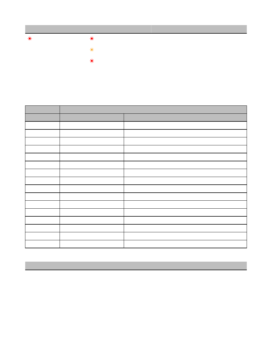
LED 1
LED 2
Gateway Status
(flashing red)
(flashing red)
Device Error
(flashing yellow)
Modbus Communication Active
(flashing red)
Modbus Communication Error
For Gateway and Ethernet Bridge systems, active Modbus communication refers to the communication between the Gateway and the
Ethernet Bridge. For GatewayPro systems, the Modbus communication LEDs refer to the communication internal to the GatewayPro. For
Gateway only systems, the Modbus communication LEDs refer to the communication between the Gateway and its host system (if appli-
cable).
Modbus Register Table
I/O Point
Modbus Holding Register
Gateway
Any Node
1
1
1 + (Node# × 16)
2
2
2 + (Node# × 16)
3
3
3 + (Node# × 16)
4
4
4 + (Node# × 16)
5
5
5 + (Node# × 16)
6
6
6 + (Node# × 16)
7
7
7 + (Node# × 16)
8
8
8 + (Node# × 16)
9
9
9 + (Node# × 16)
10
10
10 + (Node# × 16)
11
11
11 + (Node# × 16)
12
12
12 + (Node# × 16)
13
13
13 + (Node# × 16)
14
14
14 + (Node# × 16)
15
15
15 + (Node# × 16)
16
16
16 + (Node# × 16)
Specifications
Radio and General
Range
900 MHz: Up to 4.8 kilometers (3 miles)
2.4 GHz: Up to 3.2 kilometers (2 miles)
Transmit Power
900 MHz: 21 dBm (150 mW) conducted
2.4 GHz: 18 dBm (65 mW) conducted, less than or
equal to 20 dBm (100 mW) EIRP
Power
Requirements: +10 to 30V dc (Outside the USA: +12 to
24V dc, ±10%). (See UL section below for any applica-
ble UL specifications)
Consumption: Less than 2.9 W (120 mA) at 24V dc
SureCross DX80 GatewayPro
P/N 131933 Rev. F
www.bannerengineering.com - tel: 763-544-3164
5