Specifications, 3 specifications – Banner A-GAGE MINI-ARRAY Series User Manual
Page 8
8
P/N 117167 rev. A
Banner Engineering Corp.
•
Minneapolis, MN U.S.A.
www.bannerengineering.com • Tel: 763.544.3164
MINI-ARRAY
®
Two-Piece Measuring Light Screen
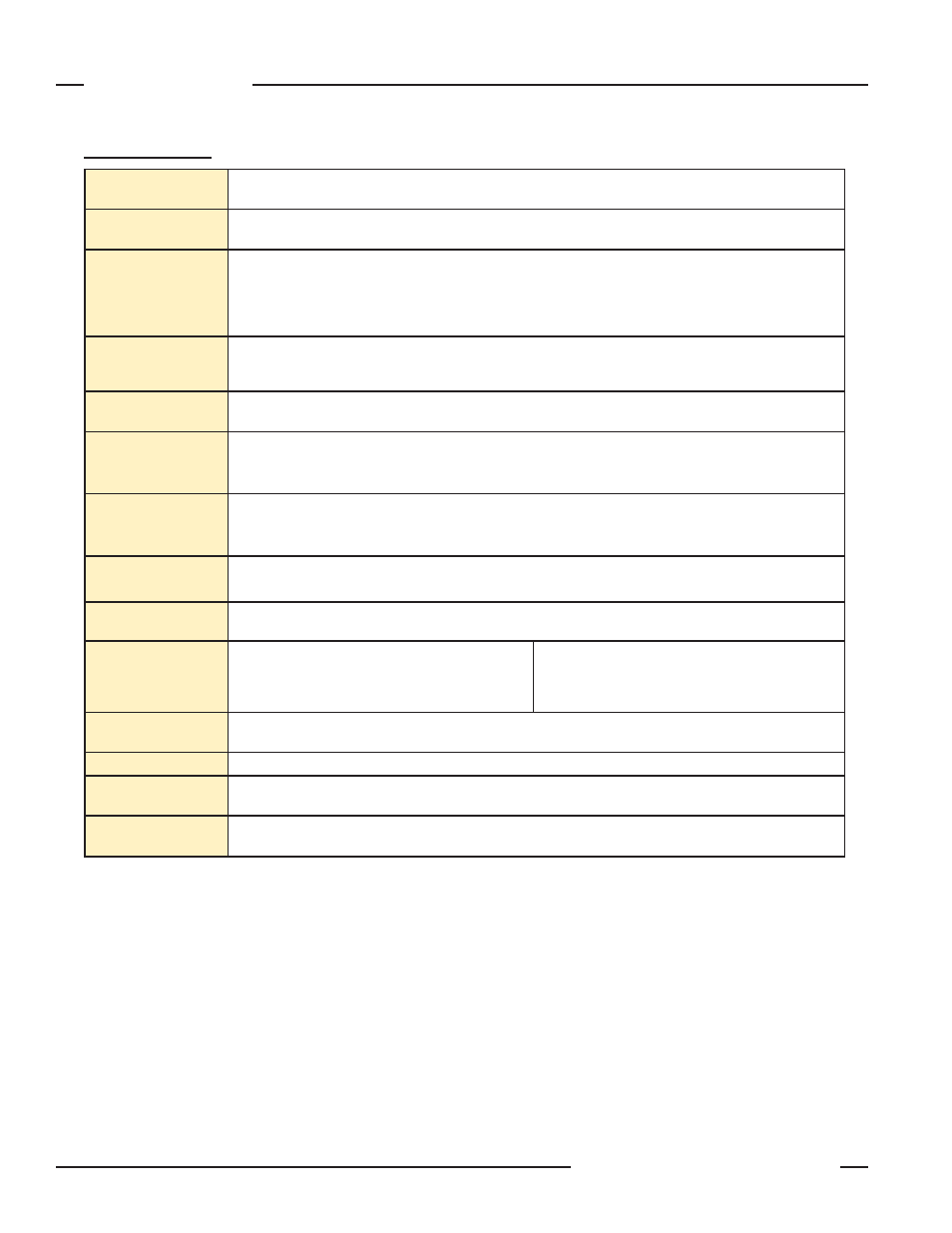
Specifications
Supply Voltage
and Power
16 to 30V dc. Maximum power 12 watts.
Supply Protection
Circuitry
Protected against transient voltages and reverse polarity
Discrete Output
Configuration
2 Discrete Outputs: Output 1 and Output 2. Outputs can be configured as either open collector NPN or PNP
transistors. For the vehicle separation application, the outputs are factory configured as NPN outputs.
Discrete Output (either NPN or PNP) ratings: Rated at 30V dc max, 150 mA max load, short circuit protected
OFF-State Leakage Current: <10 µA @ 30V dc
ON-State Saturation Voltage: <1V @ 10 mA, <1.5V @ 150 mA
Serial Data Outputs
EIA-485 interface
Baud rate 9600, 19.2 K, 38.4 K
8 data bits, 1 start bit, 1 stop bit, no parity
Controller
Programming
Via EIA-485 to PC-compatible computer running Windows
®
98, NT, ME, XP, 2000 Operating System
Emitter/Receiver
Range
Sensors < 1220 mm (4') long: 0.9 to 16.5 m (3' to 55')
Sensors ≥ 1220 mm (4') long: 0.9 to 13.5 m (3' to 45')
NOTE: Maximum range is specified at the point where 3x excess gain remains.
Minimum Object
Sensitivity
Interlaced Mode: 25.4 mm (1.0")*
Other scanning modes: 38.1 mm (1.5")
*NOTE: Assumes sensing is in middle one-third of scanning range.
Sensor Scan Time
See Section 2.1.
NOTE: Worst-case response time is twice the scan time.
Cable Connections
Emitter and receiver connections: See Figure 3-6. For QD versions, use cable listed in Section 2.2.
Emitter and receiver cables may not exceed 80 m (250') each.
Status Indicators
(see Section 3.3 for
more information)
Emitter
Red LED lights for proper operation
Receiver
Green: sensors aligned (> 3x excess gain)
Yellow: marginal alignment (1x-3x excess gain)
Red: sensors misaligned or beam(s) blocked
Environmental
Rating
NEMA 4, 13 (IEC IP65)
Construction
Aluminum housing with black anodized finish; acrylic lens cover
Operating
Conditions
Temperature: -40° to +70° C (-40° to +158° F)
Max. rel. humidity: 95% (non-condensing)
Application Notes
• The emitter and receiver sync lines (pink and white wires) will be damaged if connected to the power supply.
• The receiver EIA-485 interface (red and green wires) will be damaged if connected to the power supply.
2.3 Specifications