Appendix a, Appendix a. serial communication, Serial communication data format – Banner A-GAGE MINI-ARRAY Series User Manual
Page 13: Request sensor to scan command (command 0x53)
P/N 117167 rev. A
13
Banner Engineering Corp.
•
Minneapolis, MN U.S.A.
www.bannerengineering.com • Tel: 763.544.3164
MINI-ARRAY
®
Two-Piece Measuring Light Screen
Appendix A describes the serial communication data format and commands
that are available to serially communicate over the EIA-485 interface. The
serial commands can be used to initiate scanning, request sensor light channel
information, request system status, and request one or two sensor measurements.
The serial communication data format utilized by the sensor is described and
related to the sensor commands; examples follow.
Serial Communication Data Format
The serial communication utilizes a standard universal asynchronous receiver/
transmitter architecture. The sensor baud rate can be 9600, 19200, or 38400.
The data will have one start bit, one stop bit, no parity, eight data bits and is
transmitted least significant bit first. The serial communication string format will
consist of a start-of-header byte, a sensor-identification byte, a command byte, a
count of the data bytes, the data bytes, and a two-byte check sum.
All serial communication will follow this data format. The start-of-header byte
will always have hexadecimal value 0xF4 (244 decimal). The sensor identification
byte can have hexadecimal values ranging from 0x41 through 0x5A (65 through 90
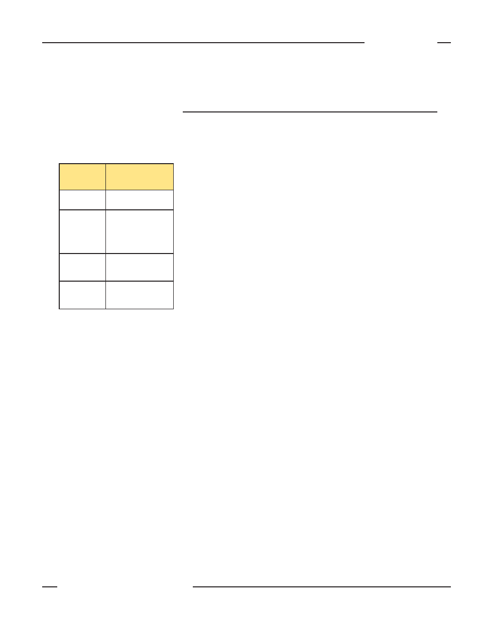
decimal). The command bytes used for the sensor are listed in Table A-1.
The count of the data bytes defines the number of data bytes that will be
transmitted for the particular command. For instance, if four data bytes are
transmitted, then the value for the number of data bytes will equal four. The actual
data bytes follow the byte representing the number of data bytes. The check sum
is a two-byte value that is calculated by summing the previous bytes in the string.
Once the sum is known, then a ones complement of the sum is calculated and
used as the string check sum value. Examples will be given in the description of
each command.
Request Sensor to Scan Command (Command 0x53)
This command will be used when the sensor is configured for host scanning. This
command is useful for instances where multiple sensors are present and sensor
cross talk is an issue. Assuming the sensor ID is 0x41, the command string would
be as follows:
Transmit string to sensor: 0xF4, 0x41, 0x53, 0x00, 0x77, 0xFE
Receive string from sensor: 0xF4, 0x41, 0x53, 0x01, 0x06, 0x70, 0xFE
This receive string would be interpreted as follows:
0xF4 is the start-of-header byte
0x41 is the sensor-identification byte
0x53 is the command requesting the sensor scan initiation
0x01 is the number of data bytes
0x06 is the valid response stating that the sensor initiated a scan
The last two bytes are the check sum in low-byte, high-byte order and calculated
as follows:
0xF4 + 0x41 + 0x53 + 0x01 + 0x06 = 0x18F.
The ones complement of 0x18F = 0xFE70.
Hence the low-byte, high-byte order would be 0x70, 0xFE.
Appendix A. Serial Communication
Appendix A
Command
Value
(Hexadecimal)
Command
Description
0x53
Request Sensor to
Scan
0x64
Request Sensor
to Transmit Each
Optical Channel
State
(0-clear, 1-blocked)
0x66
Request Sensor to
Transmit System
Status Information
0x67
Request Sensor to
Transmit One or Two
Measurement Values
Table A-1.