Installation and alignment, Mini-array, Two-piece measuring light screen – Banner A-GAGE MINI-ARRAY Series User Manual
Page 11
P/N 117167 rev. A
11
Banner Engineering Corp.
•
Minneapolis, MN U.S.A.
www.bannerengineering.com • Tel: 763.544.3164
MINI-ARRAY
®
Two-Piece Measuring Light Screen
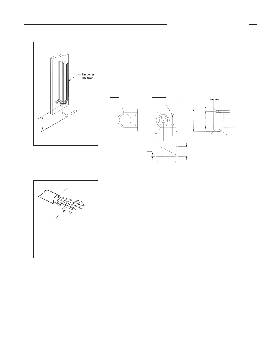
Mount the emitter and receiver in their mounting brackets (see Figure 3-1), and
position the red lenses of the two units directly facing each other. The connector
ends of both sensors must point in the same direction. Measure from one or more
reference planes (i.e., the floor) to the same points on the emitter and receiver to
verify their mechanical alignment. If the sensors are positioned exactly vertical
or exactly horizontal, a carpenter’s level may be useful for checking alignment.
Extending a straight-edge or a string between the sensors may help with
positioning. Also check by eye for line-of-sight alignment. Make any necessary final
mechanical adjustments, and hand-tighten the bracket hardware.
Figure 3-4. MINI-ARRAY emitter and receiver mounting bracket dimensions
Min. R.
34.8 mm
(1.37")
Slots have clearance
for M4 bolts (supplied)
and allow
± 30° rotation
11.9 mm
(0.47")
24.6 mm
(0.97")
57.2 mm
(2.25")
44.5 mm
(1.75")
R 6.4 mm
(0.97")
10.2 mm (2)
(0.40")
Full R (4)
38.1 mm
(1.5")
4.8 mm (2)
(0.19")
3.8 mm
(0.15")
6.4 mm
(0.25")
QD End
Non-QD End
ø 30.5 mm
(ш 1.2")
ш 13.2 mm
(ш 0.52")
ш 6.8 mm (2)
(ø 0.27")
3.0 mm
(0.12")
53.8 mm
(2.12")
Connect the shielded cables to the emitter and receiver, and route them to the
terminal location. Follow the local wiring code for low-voltage dc control cables.
The same cable type is used for both emitter and receiver (two cables required per
system). Cut the cables to length after making sure they are routed properly.
The “drain wire” is the uninsulated
stranded wire which runs between the
cable jacket and the foil shield. Remove
the foil shield at the point where the wires
exit the cable.
Figure 3-3. Emitter/receiver cable
preparation
Trim foil shield flush
with cable
Uninsulated
drain wire
13 mm (0.5") radius minimum bend
Figure 3-2. Cable clearances
Installation and Alignment