Automatic binding using the menu navigation, Setting the network id in extended addressing mode – Banner SureCross DX80 Wireless Networks User Manual
Page 4
When entering the extended address code, the digits auto fill with whatever position the rotary switch is currently in. For
example, after entering the 00 part of the extended address code 002245, the third digit auto fills with a 0 until the rotary
dial is rotated to 2.
* For devices with batteries integrated into the housing, remove the battery for one minute to cycle power to the device.
Automatic Binding Using the Menu Navigation
The easiest way to bind the Gateway to its Nodes is by triple clicking button 2 to enter automatic binding mode. If you
would prefer to begin automatic binding mode using the menu structure instead of the buttons, follow these steps.
Before making any changes to the DIP switches, disconnect the power to the devices. For devices with batteries integrated
into the housing, remove the battery.
1. On the Gateway: remove the top cover.
2. Move DIP switch 1 to the ON position.
Extended Addressing Mode is activated using DIP switch 1.
3. Apply power to the Gateway.
The Gateway's LCD displays POWER, then *RUN.
4. On the Gateway, single click button 1 to advance across the menus, stopping at the DVCFG menu.
The Gateway's LCD displays (DVCFG).
5. Single click button 2 to select DVCFG. Single click button 1 to select from the available menu options, stopping at
XADR.
The Gateway's LCD displays (XADR).
6. Single click button 2 to enter XADR mode. When the display reads (AUTO), single click button 2 again to begin the
automatic binding mode.
The LEDs flash alternately when the Gateway is in binding mode. Any Node entering binding mode will bind to this
Gateway. The Gateway's LCD displays NETWRK BINDNG.
7. On the Node: remove the top cover.
8. Move DIP switch 1 to the ON position.
Extended address mode is activated using DIP switch 1.
9. Apply power to the Node.
The Node's LCD displays POWER, then *RUN.
10. On the Node, single click button 1 to advance across the menus, stopping at the DVCFG menu.
The Node's LCD displays (DVCFG).
11. Single click button 2 to enter the DVCFG menu.
12. Single click button 1 to select from the available submenu options, stopping at XADR.
The Node's LCD displays (XADR).
13. Single click button 2 to enter the XADR submenu.
14. When the display reads (AUTO), single click button 2 to begin the automatic binding mode.
The Node enters binding mode. The Node's LCD displays NETWRK BINDNG. When the Node is bound, the LEDs are
both solid red for a few seconds. The Node cycles its power, then enters RUN mode.
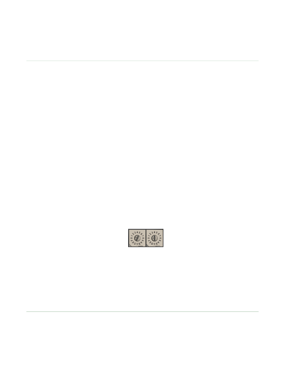
15. Use both of the Node’s rotary dials to assign a decimal Node address between 01 and 47.
The left rotary dial represents the tens digit (0–4) and the right dial represents the ones digit (0–9) of the device
address.
16. Repeat steps 7 through 15 for each additional Node that needs to communicate to that Gateway.
17. On the Gateway: single click button 1 or button 2.
When button 1 or 2 is pressed, the Gateway exits binding mode and reboots. The Gateway's LCD displays POWER, then
*RUN.
For devices with batteries integrated into the housing, remove the battery for one minute to cycle power to the device.
After making any changes to DIP switch settings, you must cycle power to the device or the DIP switch changes will not be
recognized.
Setting the Network ID in Extended Addressing Mode
Use the menu system to set the Network ID when using extended address mode.
1. From the top level menus, single-click button 1 to advance through the menus, stopping at DVCFG (Device
Configuration).
The Gateway's LCD displays *DVCFG
2. Single-click button 2 to enter the DVCFG menu options and stop at (NID).
The Gateway's LCD displays (NID)
Extended Address Mode and Binding
4
www.bannerengineering.com - tel: 763-544-3164
P/N 141340 rev A