Convergent beam mode: model oasbcv, Oasbcv – Banner OMNI-BEAM Series User Manual
Page 5
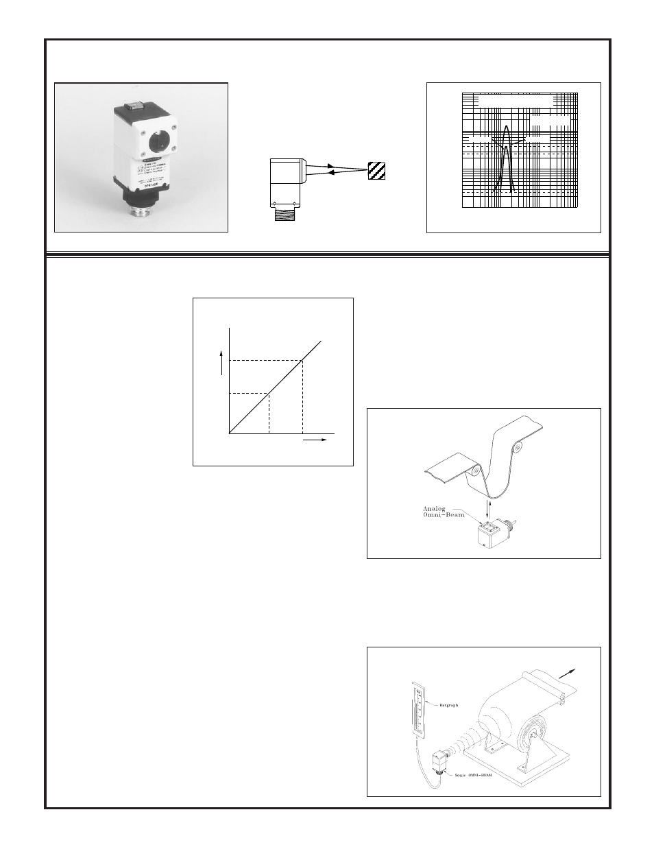
Model
OASBCV
Beam: visible red, 650nm
Maximum Response Range:
focus at 1.5 inches (38mm)
Convergent Beam Mode: model OASBCV
5
See pages 5 through 8 for a comprehen-
sive discussion on the theory and use of
analog sensors.
1
.1
DISTANCE
10
100
.1 IN
1 IN
10 IN
100 IN
Range based on 90%
reflectance white test card
OASBCV
E
X
C
E
S
S
G
A
I
N
I
Max. NULL
4
2.7
.25
Min. NULL
Figure 2. Loop control
Figure 1. Concept: analog response
Photoelectric Sensing Modes and Their Use in Analog Control
Figure 3.
Sonic
OMNI-BEAM
application
Inc
reasing voltage
Increase (or decrease)
in received light level
Sensor Output
A
B
OBJECT
.
Every analog sensing application
requires that the sensor produce a
predictable change in output that
directly corresponds with a pre-
dicted mechanical change. The
analog sensor output usually pro-
duces a measureable change in
voltage or current.
In the case of a photoelectric sen-
sor, the mechanical change within
the process being monitored must
produce a change in light intensity
at the sensor's receiver. Most ana-
log sensor applications involve the
tracking of a process represented
by a change between specific light
levels, say "level A" and "level B" (see Figure 1).
The best photoelectric sensor for any analog application is one which:
1) Senses the greatest amount of light level change between levels A and B,
2) Produces a constantly increasing or decreasing change change of output
between levels A and B.
Also, in applications where no circuitry is available to integrate or otherwise
condition the sensor output, it is often desireable or necessary that the sensor
produce an output which tracks linearly between levels A and B.
The selection of the best Analog OMNI-BEAM sensor for a specific application is
a matter of:
1) Selecting the sensor head that has the optimum optical response per the above
criteria, and
2) Configuring the sensor optics within the application to optimize these same
criteria.
An understanding of the differences between the various photoelectric sensing
modes greatly simplifies sensor selection decisions. The Banner Handbook of
Photoelectric Sensing offers a discussion of sensing modes. The following discus-
sion presents, in general terms, how each sensing mode is most commonly used for
analog sensing applications.
Diffuse mode sensor heads are primarily used for two types of applications:
1) Distance measurement over relatively long distances (i.e. several inches or
feet), or
2) Reflectivity measurement or monitoring.
Diffuse (Proximity) Sensing Mode:
models OASBD and OASBDX
Distance measurement applications include stack height control,
web loop control (Figure 2), and bin level control. Successful
photoelectric distance measurement usually demands that the
reflectivity of the material being sensed remain constant. If the
material being sensed has a specular (shiny) surface, then the angle
of the sensor to the material's surface must also remain constant.
These sensing constraints severely limit the use of photoelectric
sensors for distance measurement. For long distance measurement,
analog ultrasonic sensors (Figure 3) are often the first choice.
Ultrasonic sensors measure the elapsed time between a sound
transmission and the returned echo. Consequently, analog ultrasonic
sensors have the benefit of offering an output that is truly linear with
sensing distance.