Selecting a power block module, Specifications, Mbcc-type minifast – Banner OMNI-BEAM Series User Manual
Page 2: Qd cables, Hookup information, Model output(s) required supply voltage cable type
2
MBCC-type minifast
™
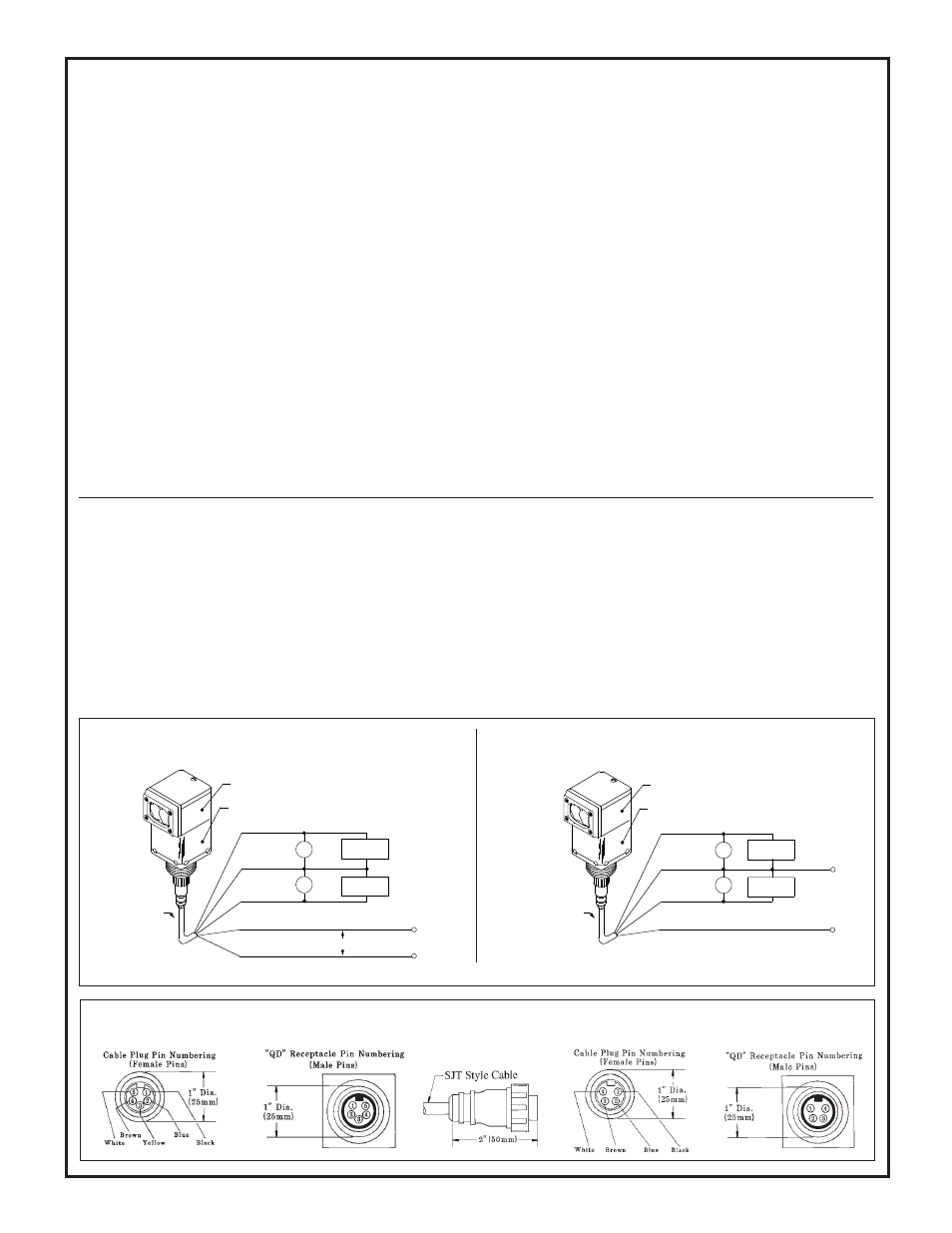
QD Cables
for QD model power blocks (purchase cables separately; see table above)
MBCC-512 Cable connector
Bottom view of power block
NOTE: If both outputs are used simultaneously, the maximum total load may not exceed 10 mA.
Side view of connector
MBCC-412 Cable connector
Bottom view of power block
Response time: Output response is the sum of the sensor's fixed R-C
time constant and the programmable R-C time constant. 63% of any
output transition will occur within the period of the total time constant.
Fixed response times are as follows:
OASBD, F, FV, FP sensor heads = R-C time constant 1.5 ms
OASBCV sensor head = R-C time constant 3.3 ms
OASBDX, FX sensor heads = R-C time constant 15.0 ms
The programmable R-C time constant is set using the switches located at
the base of the sensor head (see "Adjustment Procedure", page 3):
All switches "off" = 1 ms
Switch #3 "on" = 1 sec
Switch #1 "on" = 10 ms
Switch #4 "on" = 10 sec
Switch #2 "on" = 100 ms
If more than one switch is "on", the time constant is additive.
Adjustments:
NULL: Null is adjusted (for the condition of greatest received light) until
the #1 LED on the moving dot LED output display just turns "off" (only
the POWER indicator LED should be "on" at this point). Further decrease
the NULL adjustment until the inverting output just reaches 0 volts, or
until the non-inverting output just reaches +10V dc. Refer to the
Adjustment Procedure (page 3) and the hookup diagrams below.
SPAN: Span is adjusted to produce the desired voltage swing between the
lightest and darkest sensing conditions. Minimum guaranteed signal
contrast (i.e. minimum SPAN) which will result in a 10 volt output swing
is 1.5:1. Maximum guaranteed signal contrast (i.e. maximum SPAN) that
will result in a 10 volt output swing is 16:1.
Specifications
(continued from page 1)
Hookup Information:
OPBA3, OPBA3QD, OPBB3,
AC Input OPBB3QD Analog Output Power Blocks
Hookup Information:
OPBT3 and OPBT3QD
DC Input Analog Output Power Blocks
A power block module performs the dual functions of providing the proper operating voltage for the sensor block and of interfacing the sensor block
to the circuit to be controlled. See Specifications section (page 1) for information on power block output load capacity. Below is a list of power block
modules that may be used with the Analog OMNI-BEAM sensor block modules. Sensor block and power block must be ordered separately.
Model
Output(s)
Required supply voltage
Cable Type
OPBA3
analog solid-state voltage sourcing (2)
105 to 130V ac (50/60 Hz) 6-ft. 5-conductor PVC-covered cable
OPBA3QD
analog solid-state voltage sourcing (2)
105 to 130V ac (50/60 Hz) MBCC-512 cable required (see below)
OPBB3
analog solid-state voltage sourcing (2)
210 to 250V ac (50/60 Hz) 6-ft. 5-conductor PVC-covered cable
OPBB3QD
analog solid-state voltage sourcing (2)
210 to 250V ac (50/60 Hz) MBCC-512 cable required (see below)
OPBT3
analog solid-state voltage sourcing (2)
+15 to 30V dc, 100mA max.
6-ft. 4-conductor PVC-covered cable
OPBT3QD
analog solid-state voltage sourcing (2)
+15 to 30V dc, 100mA max.
MBCC-412 cable required (see below)
Both controls are 15-turn clutched potentiometers with slotted brass
elements, located beneath a gasketed cover on top of the sensor. A small,
flat-bladed screwdriver is required for adjustment.
Status indicators:
Located on top of the sensor head:
Power ON: a red LED lights whenever power is applied to the power
block;
Output: Ten-element moving-dot LED array indicates approximate volt-
age output.
Output connector:
6-foot attached PVC-covered cable is standard. Cable may be spliced:
order 100-foot long extension cable model EC312-100 for power block
OPBT3, or EC915-100 for power block models OPBA3 and OPBB3.
Power block models with "QD" suffix have an integral threaded standard
quick-disconnect connector. Twelve-foot long mating quick-disconnect
(QD) cables are sold separately. See table below for more information.
Construction:
Housing: molded VALOX
®
thermoplastic polyester
Top view window: transparent Lexan
®
polycarbonate
Hardware: stainless steel
When properly assembled, all components are fully gasketed.
Fully assembled unit is rated NEMA 1, 3, 4, 12, and 13.
Operating temperature range:
0 to 50
°
C (+32 to 122
°
F).
Humidity: 95% maximum relative humidity (non-condensing).
Selecting a Power Block Module
OASB Series analog sensor head
OPBA3, OPBA3QD, OPBB3, OPBB3QD power block
Load
10mA max.
V
V
BLACK (Pin 1)
YELLOW (Pin 3)
WHITE (Pin 5)
BROWN (Pin 4)
Inverting output
output common
Non-inverting output
10mA max.
Load
6 Foot, 5 Conductor
built-in cable (OPBA3,
OPBB3); or optional
MBCC-512 Q.D. Cable
(used with OPBA3QD
and OPBB3QD)
BLUE (Pin 2)
105 to 130V ac, 50/60Hz (OPBA3, OPBA3QD)
210 to 250V ac, 50/60Hz (OPBB3, OPBB3QD)
See note
See note
OASB Series analog sensor head
OPBT3 or OPBT3QD (shown) power block
Load
10mA max.
V
V
BLACK (Pin 1)
BLUE (Pin 2)
WHITE (Pin 4)
BROWN (Pin 3)
Inverting output
dc common
Non-inverting output
+15 to 30V dc
10mA max.
Load
6 Foot, 4 Conductor
built-in cable (OPBT3)
or optional
MBCC-412 Q.D. Cable
(used with OPBT3QD)