Diffuse (proximity) mode: models oasbd and oasbdx, Oasbdx, Adjustment procedure – Banner OMNI-BEAM Series User Manual
Page 3: Analog omni-beam sensors, 3model, Oasbd, Model
3
Model
OASBDX
Beam: infrared, 880nm
Maximum Response Range
(at maximum NULL and maximum SPAN):
12 feet (3,7m)
1) Before adjusting the NULL and SPAN, slide the OALM board out from the base of the sensor
head and set the output response time at the DIP switch. Refer to the photo (below right) and the
information printed on the OALM board. Switch settings are given in the Specifications section
(page 2, top). Longer time settings are useful for "smoothing" sensor response. Slide the OALM
board back into the sensor head.
2) Begin with the sensor mounted at the sensing position and connected, per the hookup diagrams
on page 2, for the desired output (inverting or non-inverting). The most precise adjustment is attained
by using a voltmeter connected to monitor the desired
output, as shown in the hookup diagrams. Present the
"lightest" expected sensing condition to the sensor (the
condition that results in the most light seen by the receiver).
Next, perform either step #3 or step #4.
3) To adjust the inverting output: monitor the voltage
on the black wire. Adjust the NULL control to the point
where the output just reaches 0 volts*. Then present to the
sensor the "darkest" expected sensing condition (the condi-
tion that results in least light seen by the receiver), and adjust
the SPAN control to just reach 10 volts output.
4) To adjust the non-inverting output: monitor the
voltage on the white wire. Adjust the NULL control to the
point where the output just reaches 10 volts. Then present
to the sensor the "darkest" expected sensing condition (the condition that results in the least light seen by the receiver),
and adjust the SPAN control to just reach 0 volts* output.
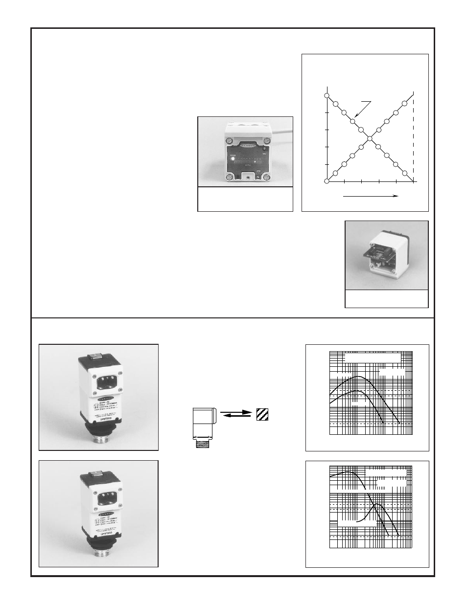
As can be seen from the graph (above, right), the slopes of the two 0-to-10V outputs are mirror-images of each other,
and the plots intersect at 5 volts output. When the 0 and 10 volt points of one output have been properly set, the other
output will track very close to the predicted values.
Other voltage ranges may be used. The practicality of doing so depends upon conditions specific to each individual
application. Substitute the lower voltage for "0 volts", and the higher voltage for "10 volts" in the preceding
adjustment instructions. When a range of other than 0 to 10 volts is used the NULL and SPAN controls will no longer
be non-interactive. If you require further assistance, contact your Banner field sales representative or a factory
applications engineer.
The OALM analog board slides
easily in and out of the sensor head.
Diffuse (Proximity) Mode: models OASBD and OASBDX
1
.1
DISTANCE
10
100
Range based on 90%
reflectance white test card
1 IN
OASBDX
10 IN
100 IN
100 IN
E
X
C
E
S
S
G
A
I
N
I
Max. NULL (upper DISTANCE scale)
4
2.7
.25
Min. NULL
(lower DISTANCE scale)
.1 IN
1 IN
10 IN
1000 IN
1
.1
DISTANCE
10
100
.1 IN
1 IN
10 IN
100 IN
Range based on 90%
reflectance white test card
OASBD
E
X
C
E
S
S
G
A
I
N
I
4
2.7
.25
Max. NULL
Min. NULL
0
2
4
6
8
10
Output (V dc)
Output Indicator
LEDs
Non-inverting output
3
Inverting output
Darkest
condition
Lightest
condition
Light signal strength
1
5
10
2
3
4
6
7
8
9
1
2
3
4
6
7
8
9
10
0
0%
60%
40%
100%
20%
80%
Adjustment Procedure,
Analog OMNI-BEAM Sensors
Top view of Analog OMNI-BEAM show-
ing the NULL and SPAN controls and the
moving-dot LED display.
The Analog OMNI-BEAM's moving-dot
LED array indicates approximate output
voltage and relative light signal strength.
Model
OASBD
Beam: infrared, 880nm
Maximum Response Range
(at maximum NULL and maximum SPAN):
36 inches (0,9m)
NOTE: The target used to plot the OSBD
and OSBDX response curves is a 90% re-
flectance white test card which measures 16
inches by 20 inches (400mm x 500mm).
Actual sensor response must consider both
the relative surface reflectivity and the ac-
tual reflective surface area of any target.
OBJECT
*Adjust the pot for minimum voltage near 0 volts dc. Voltmeter may not indicate exactly 0 volts.