Installation, Figure 1. example—correct positions, Figure 2. example—incorrect positions – Banner PVA Pick-to-Lights User Manual
Page 3: Figure 3. maximum off-axis misalignment
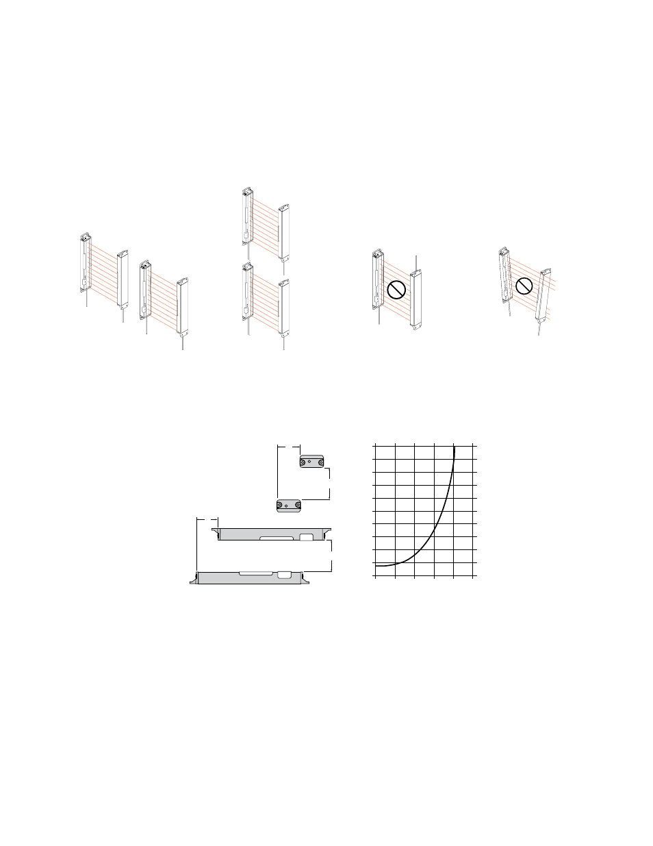
Installation
Multiple sensor pairs located farther than the sensor's effective maximum range (approximately 2 m or 6.5 ft) from one another are unlike-
ly to cause crosstalk problems. However, when multiple sensor pairs are mounted in a confined area, take care to avoid crosstalk be-
tween them. To avoid crosstalk:
• Alternate the relative position of adjacent emitter/receiver pairs.
• Alternate the Frequency configuration of adjacent pairs.
Mount emitter and receiver pairs parallel, with both cable ends pointing the same direction.
M
O
D
E
Emitter
Receiver
Receiver
Emitter
M
O
D
E
M
O
D
E
Emitter
Receiver
M
O
D
E
Receiver
Emitter
Figure 1. Example—Correct Positions
Receiver
Emitter
MODE
Cable ends pointing in opposite directions
MODE
Emitter
Receiver
Non-parallel orientation
Figure 2. Example—Incorrect Positions
0
0
0.2
0.4
0.6
0.8
1.0
1.2
1.4
1.6
1.8
2.0
250
200
150
100
50
Sensor Separation – Y
(Meters)
Horizontal Misalignment
Vertical Misalignment
Maximum Off-axis Distance – X
(Millimeters)
X
Y
X
Y
Figure 3. Maximum Off-Axis Misalignment
PVA Pick-to-Light Array
P/N 52088_web
Rev. E
www.bannerengineering.com - tel: 763-544-3164
3