13 communication diagrams for automation – Metrohm 797 VA Computrace User Manual
Page 76
2 Installation
797 VA Computrace / Hardware-Manual 8.797.8001EN
68
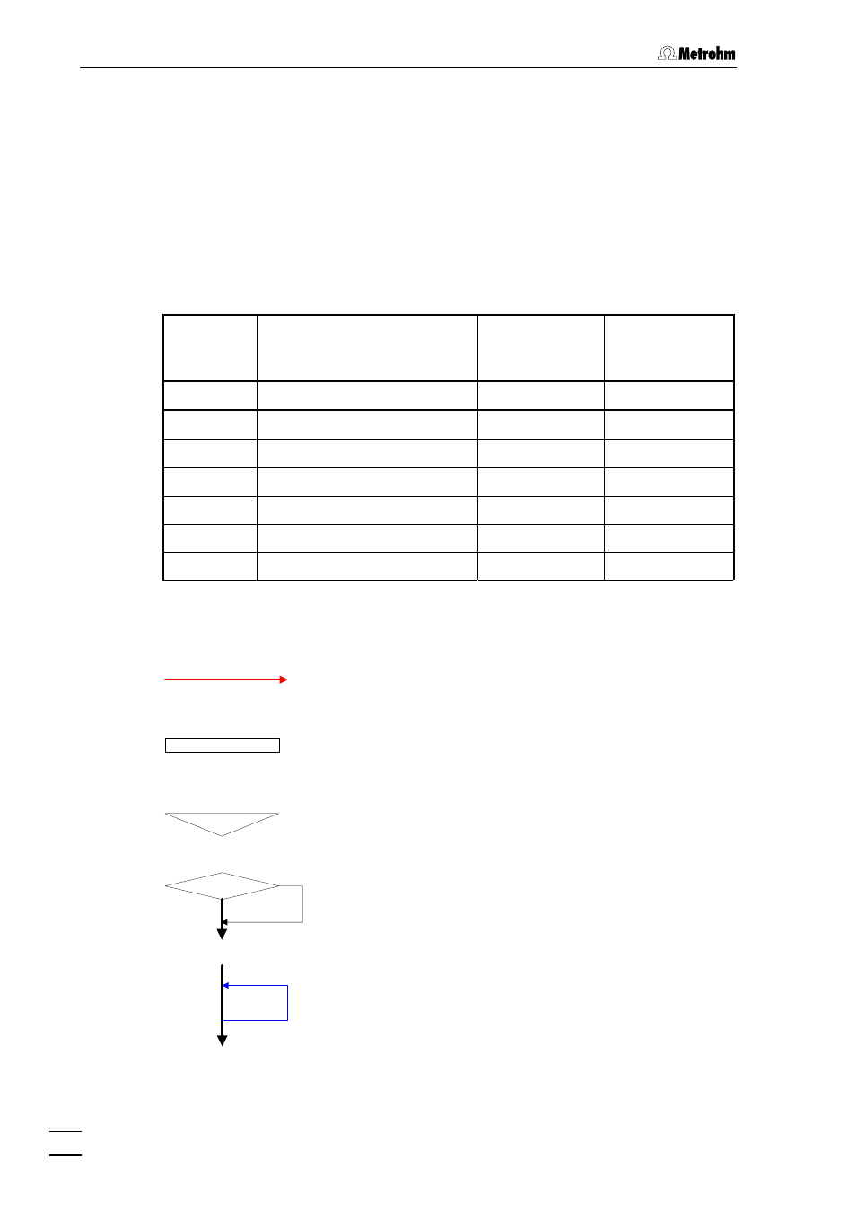
2.13 Communication diagrams for automation
In this chapter, sequence diagrams are used to describe the communication between
the devices for automation with a 838 Advanced Sample Processor.
The communication sequence depends on the selected Calibration technique in the
window
WORKING METHOD SPECIFICATION
.
The 797 VA Computrace acts as master.
The TTL's used in the diagram match with the following connections:
TTL
797 VA Computrace
838 Advanced
Sample
Processor
731 Relay Box
1
Pin 3 (End of sample)
Pin 10 (Input 3)
2
Pin 4 (End of sample table)
Pin 24 (Input 6)
3
Pin 5 (Start)
Pin 12 (Input 7)
4
Pin 6 (Set Control line)
Pin 22 (Input 2)
5
Pin 7 (Siphoning)
Pin 7 (Output 9)
6
Pin 8 (Rinsing)
Pin 8 (Output 10)
7
Pin 17 (Scan Control line)
Pin 5 (Output 0)
Legend to the communication diagrams (Section 2.13.1 - 2.13.6):
NO
YES
Signal wird von einem Gerät
an ein anderes gesendet
Sequenz-Block (der im Diagramm
nicht detailliert beschrieben wird)
Warten eines Gerätes auf ein
eintreffendes Signal
Alternativer Sequenz-Ablauf
Ein- oder mehrmalige Wiederholung des Se-
quenz-Teils zwischen Pfeilanfang und -ende