11 control lines, 12 connection of peripherals – Metrohm 797 VA Computrace User Manual
Page 75
2.11
Control lines
797 VA Computrace / Hardware-Manual 8.797.8001EN
67
For software settings and measurement procedures: see Software Manual 797 sec-
tion 8.6, and Online-Help of the <797 VA Computrace Software> section Brightener
Analysis with the 838 Advanced Sample Processor and LAT.
2.11 Control
lines
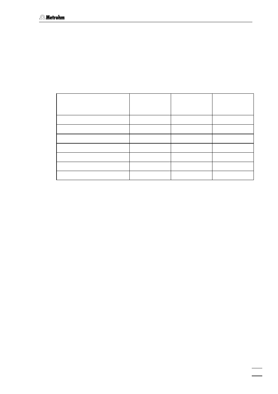
Control lines for 863 Compact Autosampler, 766 Sample Processor, 838 Advanced
Sample Processor and 731 Relay Box are listed in the table below:
797 VA Computrace
863 Compact
Autosampler
838 Advanced
Sample
Processor
731 Relay Box
Pin 3 (End of sample)
Pin 10 (Input 3)
Pin 4 (End of sample table)
Pin 24 (Input 6)
Pin 5 (Start)
Pin 12 (Input 7)
Pin 6 (Set Control line)
Pin 22 (Input 2)
Pin 22 (Input 2)
Pin 7 (Siphoning)
Pin 7 (Output 9)
Pin 8 (Rinsing)
Pin 8 (Output 10)
Pin 17 (Scan Control line)
Pin 5 (Output 0)
2.12 Connection of peripherals
The USB Connections (19) USB1 and USB2 on the backside of the 797 VA Compu-
trace Stand serve as USB-distributor of the connected PC. Any USB-instrument (e.g.
printer or 846 Dosing Interface) can be operated with these connections.
For connection and installation of a particular instrument read the respective “Instruc-
tions for Use” of the instrument and operating system.