Parts description – Bully Dog 40300 PMT advanced vehicle downloader, controller, monitor and gauge User Manual
Page 6
5
Intr
odu
ctio
n
PM
T In
sta
llati
on
Op
era
ting
Ins
tru
ctio
ns
Inte
rne
t U
pda
tes
App
end
ix
PARTS DESCRIPTION
Par
ts D
escription
paRTs DesCRIpTION
This section describes each of the parts in the Bill of Materials, the descriptions provide a physical set of
attributes and a purpose for each part. The parts descriptions also list everything that is included in each
assembly.
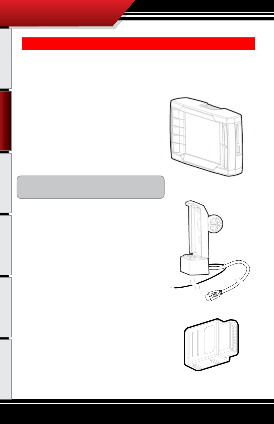
The pMT Head Unit
The main component is the PMT Head Unit. The Head Unit is
the interface in which you control vehicle performance pa-
rameters. It is also the brains that will save vehicle activity
and defuel a vehicle. Notice that the head unit has: seven to-
tal buttons, five on the left side and two on the right, a large
color screen, an electronic plug for docking on the bottom and
a snap hinge on the top also used for docking. Note that this is
the last piece that you will install.
Note: PMT includes a SD card inserted in the side of
the Head unit.
pMT Cradle with Cradle Cable and power Wire
The cradle itself is the docking station for the PMT Head
Unit. It acts as the means of communication for the PMT.
Notice that two wires come out of the bottom back side of
the cradle, the Cradle Cable and the Power Wire. During the
installation, the Cradle Cable runs to the OBDII Adapter Plug
and the Power Wire runs to the vehicle fuse box.
OBDII adapter plug
The OBDII Adapter is rectangular and has a total of four
electronic ports. The largest port on the top of the adapter
plugs into the vehicle OBDII port. The three smaller ports on
the sides include: a Cradle Cable port on one side, and on the
opposite side a 4 Pin PCH Cable port and a 5 Pin Peripheral
port. The main purpose of the OBDII Adapter Plug is to act
as a hub for all communication lines between the PMT and
the vehicle.