Pmt installation – Bully Dog 40300 PMT advanced vehicle downloader, controller, monitor and gauge User Manual
Page 27
26
PMT INSTALLATION
Intr
odu
ctio
n
Par
ts D
escription
Op
era
ting
Ins
tru
ctio
ns
Inte
rne
t U
pda
tes
App
end
ix
seCTION 4:
INsTaLLING THe pOWeR WIRe
In this section you will run the Power Wire coming from the PMT Cradle to the vehicle fuse box and
connect it to the fuse locations specified below. The fuse location for the Power Wire is different on
each vehicle application.
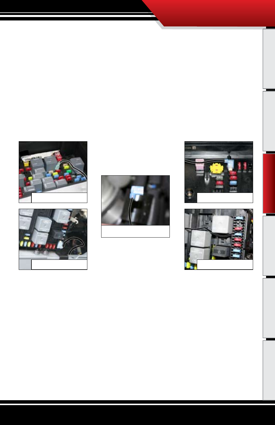
CONNECTING THE POWER WIRE:
1. Locate the fuse box: Ford fuse boxes are located under the dash inside the cab of the vehicle; Dodge
and GM fuse boxes are located on the driver’s side of the vehicle inside the engine bay. Please see your
owner’s manual for more details on fuse box locations. Once inside the fuse box, locate the appropriate
fuse depicted in the vehicle-specific pictures below.
2. Remove the fuse, indicated in the pictures, and insert the fuse jack. Make sure that the fuse jack
is placed on the dead side of the fuse to ensure that the PMT is protected by the fuse. Use a volt
meter to verify the dead side of the fuse. With the fuse pulled and the truck powered on but not
started, the volt meter should read 0 volts on the fuse jack to ground. Problems that can occur
if the incorrect fuse is used for this connection: the power may stay on continuously even with
the key off; or, the PMT can receive power at the incorrect time of the power-on/starting cycle
of the vehicle.
3. If installing on a Dodge or a GM, run the power wire through the fire wall before preparing the
Power Wire. Prepare the Power Wire by stripping the end of the wire about ¼”. Connect the blue
90° connector to the end of the Power Wire using crimping pliers.
4. Connect the Power Wire to the fuse jack, place the fuse back into the slot, and close the fuse box.
‘03-’07 Dodge: Fuse #28
‘03-’05 Ford: Fuse #33
‘0-’07 GM: Fuse “ING E”
‘06-’07 Ford: Fuse #26
Power Wire w/90º Connector
PM
T In
sta
llati
on