Resistor servicing, Resistor removal, Figure 9 load exploded view – Bird Technologies 8640B Series User Manual
Page 34
Maintenance
23
Resistor Servicing
The load is designed to be quickly and easily repaired in the field. If a
significant change in the dc resistance is noted or if the resistor
should fail, inexpensive replacement resistors are available.
Resistor Removal
Numbers in brackets [ ] refer to the labeled parts in Figure 9.
1. Disconnect the load (see “Load Removal” on page 18).
2. Turn the load on end with the hose fitting up.
WARNING
Disconnect the unit from all power sources before servicing.
The unit may be energized from multiple sources.
The potential for electric shock exists.
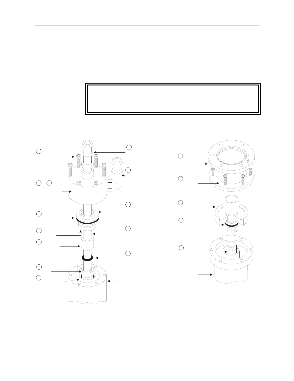
Figure 9
Load Exploded View
1/4-20 x 2-1/2
Socket Head Cap Screw (6)
Water Chamber With
O-Ring Inner Seal
Outer O-Ring
Inner O-Ring
Resistor Sleeve
Resistor
Outer Flow Tube
Load Housing
O-Ring
Inner Flow Tube
Ground Cap Assembly
Hose Fitting 90°
Hose Fitting Straight
6
3 and 4
2
7
1
5A
5
10
9
8
17
9A
Load Housing
Resistor
Center Conductor
Assembly
1/4-20 x 1-1/2
Socket Head Cap Screw (6)
Outer Conductor
Assembly
Resistor Fitting Seal O-Ring
12
16
11
1
15