Bendix Commercial Vehicle Systems C-300N HYDRAULIC POWER STEERING1/99 User Manual
Page 7
7
upon the piston surface eliminates much of the pistons
resistance to movement. Spring force exerted by the torsion
bar causes the ball screw to rotate as piston resistance is
removed. As the ball screw rotates, the relative groove
displacement is eliminated and the rotary valve returns to a
neutral position.
Moderate effort at the steering wheel produces smaller valve
displacements and lower power assist, thus providing good
steering feel. At Increased displacements, the pressure rises
more rapidly giving increased power assistance and quicker
response. Maximum pressure is developed after
approximately 3
0
displacement giving a direct feel to the
steering. Groove displacement is limited by the clearance
of the stop spline mesh between the input shaft and ball
screw. The splines take up the steering movement while
allowing the torsion bar to hold the groove displacement.
The torsion bar and stop splines form two parallel means of
transmitting the steering torque. When no steering torque
is applied, the torsion bar returns the valve grooves to a
neutral position allowing the pressurized oil to flow to the
return line. Figures 5 & 6.
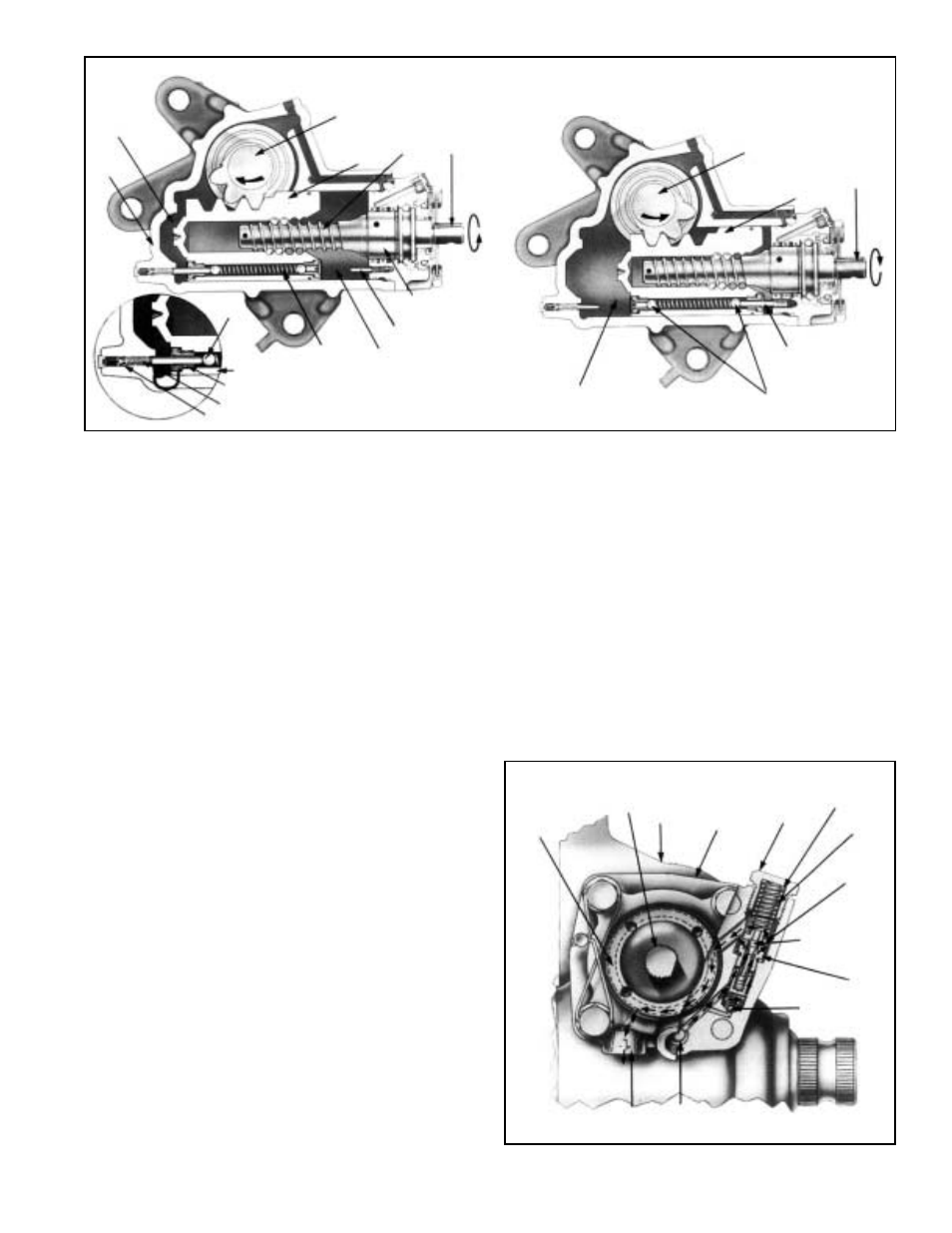
STEERING LIMITING VALVE OPERATION
In steering gears equipped with steering limiting valve, power
assisted movement of the piston within its bore is limited by
poppet valves installed in both piston faces. As the piston
approaches its extreme travel in either direction, a stem
unseats the steering limiting poppet valve. Some hydraulic
power assist is removed as pressurized oil passes around
the poppet valve to the other side of the piston and to the
return line. Continued movement of the piston will result in
removal of increasing amounts of power assist and cause
increased steering effort. Steering limiting reduces the
maximum power assist that can be transmitted to the axle
steering linkages and components. Figure 7 When this feature
is incorporated in the C-300N, only one of the two steering
limiting stems is externally adjustable. Both steering limiting
stems in the C-500N are externally adjustable. Figure 4.
PRESSURE RELIEF VALVE OPERATION
The pressure relief valve is an option. Located in the valve
body, the pressure relief valve limits hydraulic pressure
within the power steering gear to a preset maximum. While
the setting of the pressure relief valve may be adjusted to
various levels depending upon part number and application,
it is always set to a pressure lower than the relief valve on
the power steering pump. Figure 8.
FIGURE 7 - STEERING LIMITING POPPET VALVE OPERATION
HOUSING
PRESSURIZED SIDE
DURING RIGHT TURN
INPUT
SHAFT
LIMITING
STEM
BALL
SCREW
POPPET SEAT
RETURN
SIDE OF
PISTON
O-RING
OUTPUT
SHAFT
POPPET VALVES
(STEERING LIMITING)
PISTON
SPINDLE ASSEMBLY
OUTPUT
SHAFT
INPUT
SHAFT
PISTON
PISTON
ADJUSTABLE STEM
POPPET
VALVE
LIMITING
STEM
PRESSURIZED SIDE
OF PISTON DURING
LEFT TURN
POPPET VALVE
SPRING
EXTREME LEFT TURN POSITION POPPET VALVE OPEN
EXTREME RIGHT TURN POSITION POPPET VALVE OPEN
FIGURE 8 - PRESSURE RELIEF VALVE OPERATION
INPUT
SHAFT
OIL
RETURN
CHANNEL
POWER
STEERING
GEAR
HOUSING VALVE
BODY
ADJUSTING
SHIMS
SPRING
PRESSURE
RELIEF
VALVE
PLUG
SPRING
SEAT
BYPASS
VALVE
PRESSURE
RELIEF VALVE
& PISTON
OIL SUPPLY
PORT
OIL RETURN
PORT