Bendix Commercial Vehicle Systems C-300N HYDRAULIC POWER STEERING1/99 User Manual
Page 13
13
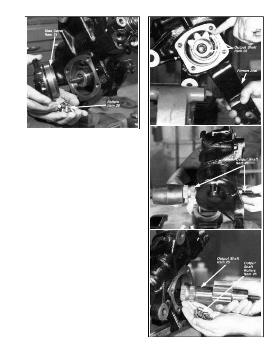
FIGURE 18 - SIDE COVER & ROLLER BEARINGS
FIGURE 19 - REMOVING OUTPUT SHAFT
5. Loosen and remove the lock nut (32) from adjusting
screw (33) on the side cover(31) using a 19mm wrench.
6. Scribe a line or otherwise mark the relationship of the
side cover (31) to housing (22). Using a 19mm wrench,
remove the four bolts (49) that secure the side cover to
the housing. Figure 17
7. Separate the side cover from the housing by turning the
adjusting screw (33) clockwise with a 7mm socket.
Continue turning the adjusting screw until the side cover
can be removed from the housing (22). When the side
cover is removed from the housing the 17 rollers in the
side cover bearing (26) will fall out loose. These rollers
MUST NOT BE INTERCHANGED with the rollers in the
housing bearing which is identical. Figure 17 & 18.
CAUTION: Do not attempt to remove the outer race of
the roller bearing from the side cover.
8. Install the pitman arm and use it to center the piston(23)
and output shaft (25) gear teeth inside the side cover
opening of the housing. Remove the pitman arm and
then remove the output shaft by tapping gently on the
splined end with a soft mallet.
When the output shaft is removed from the housing, the
17 rollers in the housing bearing (26) will fall out loose.
These rollers MUST NOT BE INTERCHANGED with the
rollers in the side cover bearing which is identical.
CAUTION: Do not attempt to remove the outer race of
the roller bearing from the housing. Figure 19