Bendix Commercial Vehicle Systems C-300N HYDRAULIC POWER STEERING1/99 User Manual
Page 27
27
PART NUMBER 106773
PRESSURE RELIEF VALVE TEST PLUG ASSEMBLY
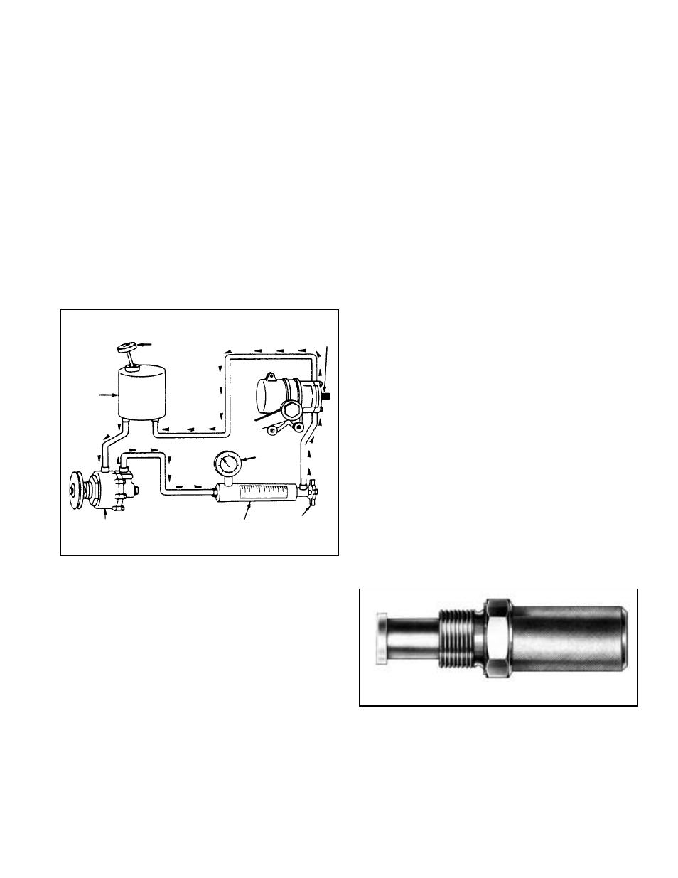
FLOW METER
FIGURE 56 - FLOW METER & PRESSURE GAUGE
INSTALLATION
FIGURE 57 - PRESSURE RELIEF VALVE TEST PLUG
ASSEMBLY
1. Adjust the axle stops using the vehicle manufacturers
specifications.
2. Install a pressure gauge or gauge and flow meter
combination in the pressure (supply) line between the
power steering pump and steering gear. Figure 56. Note:
If a shut off valve is part of the gauge or gauge/flow
meter, make certain the valve is open.
Caution: During the procedure that follows, use
extreme care not to operate the power steering pump
at its relief valve pressure for more than a few seconds
at a time. Extended operation at pump relief pressure
will result in excessive heat and subsequent damage
to the system. A thermometer installed in the pump
reservoir will allow temperature checks to assure the
maximum pump and gear temperatures are not
exceeded.
3. Start the engine and gently turn the steering wheel to
the axle stop in both directions while observing the
pressure gauge and the direction of the wheel cut (right
or left). Read the possible reactions described below
and take the appropriate action.
A. Gauge pressure drops noticeably just prior to the
steering mechanism contacting the axle stop in one
turning direction only. In the opposite steering
direction, gauge pressure increases to pump or gear
relief pressure as the steering mechanism contacts
the axle stop.
If the steering gear being adjusted is a C-300N, this
is the desired reaction and indicates the turning
direction controlled by the externally adjustable
steering limiting stem. The turning direction that
registers pump relief is the one controlled by the
externally adjustable steering limiting stem. Proceed
to Step 4.
If the steering gear being adjusted is a C-500N, make
certain that both externally adjustable steering
limiting stems are adjusted out (counter clockwise)
to within 5 turns of being removed, then retest.
B. Gauge pressure does not drop prior to axle stop
contact in either turning direction, and pump or gear
relief pressure is noted upon axle stop contact.
If the steering gear being adjusted is a C-300N, this
reaction indicated the internally adjustable steering
limiting stem is improperly adjusted, or broken, or
the steering limiting valve (9 & 17) is malfunctioning.
The C-300N must be removed and disassembled.
If the steering gear being adjusted is a C-500N, this
is the desired reaction. Proceed to Step 4.
C. If gauge pressure drops prior to axle stop contact
both directions, turn the externally adjustable
steering limiting stem counter-clockwise and repeat
the test until reaction A is obtained for C-300N or
reaction B is obtained for C-500N.
4. Return the steering to a neutral straight ahead position
and turn the externally adjustable steering limiting stem
clockwise to its full travel.
5. Gently turn the steering wheel in the direction effected
by the externally adjustable steering limiting stem until
the axle stop is contacted. Pressure registered on the
gauge should be relatively low.
With the steering wheel held to maintain axle stop
contact, turn the stroke limiting stem counterclockwise
until the gauge pressure JUST begins to rise or until
the gauge pressure specified by the vehicle
manufacturer is obtained.
Note: A rise in pressure on the gauge while turning
the stroke limiting stem counterclockwise indicates
that the stroke limiting valve is beginning to close.
Continued turning of the stem will cause the valve to
close and the pressure to rise until the valve is
completely closed and the pressure rises to the gear
or pump relief setting.)
6. After adjustment of the stroke limiting is complete, install
the plug(s) (21) in the stem bore(s).
SHUTOFF
VALVE
GAUGE
POWER
STEERING GEAR
THERMOMETER
OIL
RESERVOIR
POWER STEERING
PUMP