Bendix Commercial Vehicle Systems C-300N HYDRAULIC POWER STEERING1/99 User Manual
Page 15
15
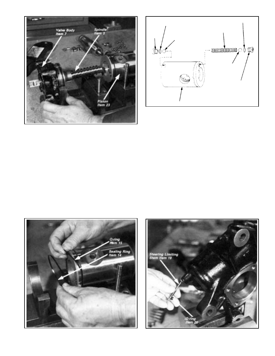
FIGURE 25 - REMOVING/INSTALLING SPINDLE
FIGURE 27 - REMOVING/INSTALLING STEERING LIMITING
COMPONENTS
FIGURE 26 - REMOVING/INSTALLING PISTON SEALING RING
& O-RING
FIGURE 28 - REMOVING/INSTALLING STEERING LIMITING
STEM
SEALING WASHER
ITEM 18
SEALING WASHER
ITEM 18
SPRING ITEM 16
VALVE
SEAT
ITEM 17
BALL
ITEM 9
VALVE
SEAT
ITEM 17
PISTON ITEM 23
BALL
ITEM 9
Separate the valve body and spindle from the piston.
Check the inside of the piston for any stray balls (9)
that may not have been removed in the operation above.
A total of 26 balls, 7 from the ball tube and 19 from the
piston, should be accounted for. Figure 25
12. Remove the sealing ring (14) and O-ring (15) below it
from the groove in the piston (23). Figure 26
13. If the steering gear is not equipped with a steering limiting
valve feature, disregard steps 13-15. Remove either of
the steering limiting valve seats (17) and sealing washer
(18) from the piston. Either a Phillips or straight blade
screwdriver will be required, depending upon which of
the two styles of body is in use. Figure 27
Note: Care must be taken during this operation since
damage to the screwdriver slot will make removal
difficult.
14. Remove one of the two balls (9), the spring (16), then
the remaining ball (9). Referring to the previous step,
remove the remaining steering limiting valve seat (17)
and its sealing washer(18) from the other end of the
piston. Figure 27
HOUSING & SIDE COVER DISASSEMBLY
15. Remove the steering limiting stem protective plug (21)
from the housing. Using a screwdriver remove the stroke
limiting valve stem (19) from the housing and separate
the O-ring (20) from the stem. Figure 28
16. Remove the O-ring (27) from the side cover (31). Remove
the seal (29) and its split nylon backup ring (28) from