Bendix Commercial Vehicle Systems COMPACT 500 9/87 User Manual
Page 4
4
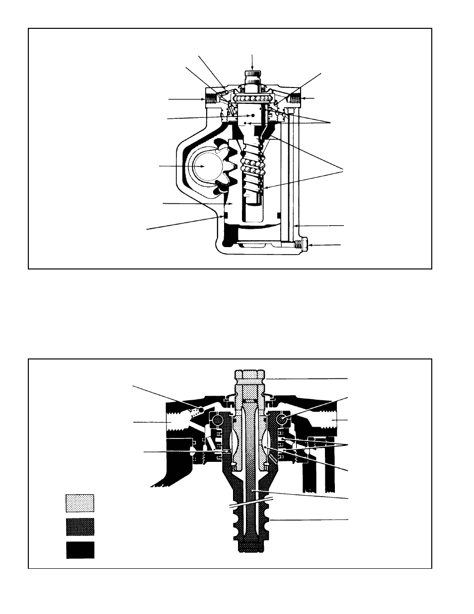
FIGURE 2
SEAL AND
GLIDE RINGS
SPINDLE ASSEMBLY W/
ROTARY VALVE (BALL
SCREW ASSEMBLY)
DELIVERY FROM
ROTARY VALVE
OIL OUT
INPUT
SHAFT
VALVE NUT
BY PASS
VALVE
CIRCULAR
GROOVES
OIL IN
ROTARY
VALVE
SUPPLY
OUTPUT
SHAFT
PISTON
OIL PASSAGE
DRAIN PLUG
FIGURE 3
MECHANICAL-
HYDRAULIC PARTS
CIRCULAR
GROOVES
OIL OUTLET
INPUT SHAFT
BEARING
BY PASS
VALVE
LONGITUDINAL
GROOVES
OIL INLET
PARTS WITH NO
MOVEMENT
MECHANICAL
MOVEMENT PARTS
CONNECTING POLE
TORSION BAR
BALL SCREW
bar results in the input shaft rotating slightly in advance of
the ball screw. The six pairs of grooves that form the rotary
control valve are displaced from their neutral flow position.
As steering effort increases so does the amount of
displacement. Depending on the direction steered, the groove
displacement of the input shaft directs hydraulic oil through
the appropriate drilled passages in the ball screw to one
side or the other of the piston. Hydraulic pressure acting
upon the piston surface eliminates much of the pistons
resistance to movement. Spring force exerted by the torsion
bar causes the ball screw to rotate as piston resistance is
removed. As the ball screw rotates, the relative groove