Bendix Commercial Vehicle Systems COMPACT 500 9/87 User Manual
Page 16
16
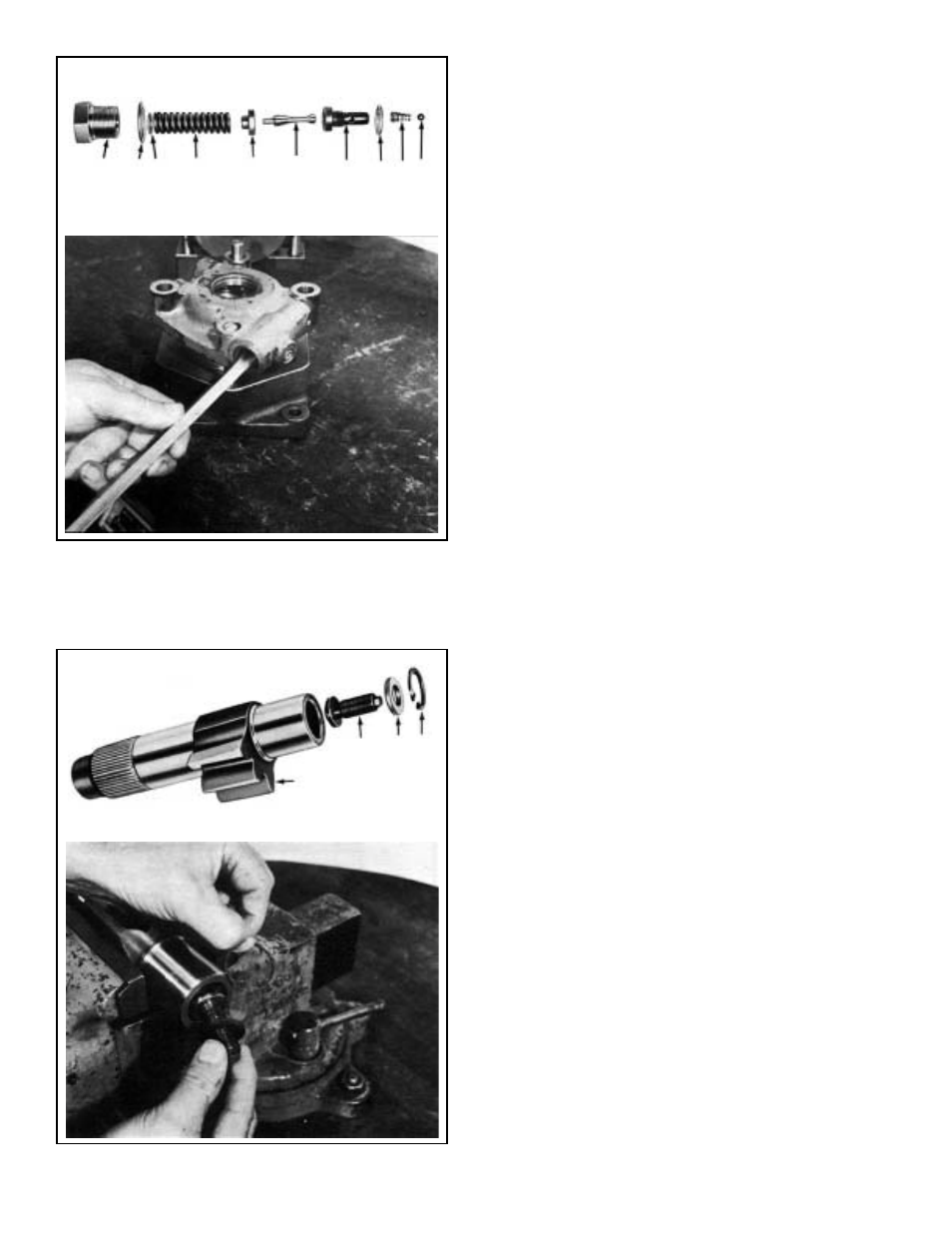
OUTPUT SHAFT DISASSEMBLY
20. Remove the snap ring(38), the adjusting screw spacer(37)
and the adjusting screw(36) from output shaft. (See
Figure 29)
SPINDLE DISASSEMBLY
CAUTION: Do not attempt disassembly of the spindle
assembly which contains the rotary valve. Individual
replacement parts are NOT available for this
assembly. It must be treated as a single component.
CLEANING AND INSPECTION
CLEANING
Wash all parts individually in clean solvent and dry thoroughly.
All non-metallic parts should be discarded and replaced with
new.
INSPECTION
Visually inspect all parts carefully paying particular attention
to:
1. Bearings and bearing surfaces including inner and outer
races and balls.
2. Sector gear and piston teeth.
3. Output and input shaft.
4. Exterior of spindle and interior of piston and recirculating
balls.
5. Exterior of piston and housing bore.
NOTE: Minor scuffing of the piston exterior and
housing bore can be considered normal. If deep
scoring is detected, the affected parts should be
replaced as leakage will occur and steering control
and reaction will be affected. Do not attempt honing
or boring of these parts as leakage rates will increase.
6. Pitman arm.
7. Housing and mounting lugs.
8. Valve body and porting. Parts found broken, cracked,
distorted or fatigued must be replaced. Cause for the
replacement of any part should be investigated and
corrected to prevent reoccurrence.
IX. REASSEMBLING THE POWER STEERING
UNIT
To ensure a correct fault-free operation of the power steering
unit, after all parts have been cleaned and faulty ones
replaced, the following assembly procedure should be
followed. The appropriate maintenance kit or kits should be
obtained prior to assembly. Should any of the 17 ball bearing
balls require replacement, replace them all at once; proceed
similarly in case any of the 26 recirculating balls need
replacement. Failure to follow this procedure strictly may
result in a faulty operation of the power steering unit.
FIGURE 28
3
4 5
6
7
8
9
10 11 12
FIGURE 29
35
36
37 38