Bendix Commercial Vehicle Systems COMPACT 500 9/87 User Manual
Page 17
17
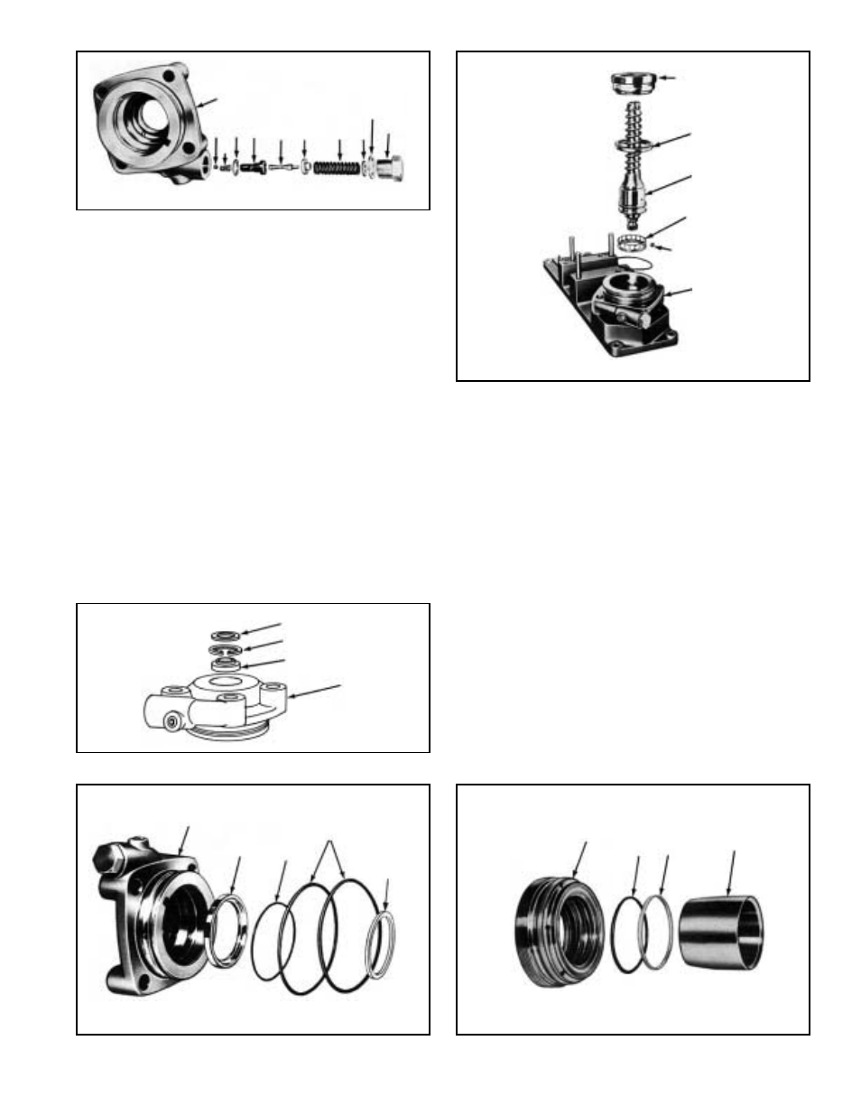
FIGURE 33
VALVE BODY (REFER TO FIGURE 30)
1. Place the valve body(16) in a vise and lightly tighten on
the cast surface. Install the ball(12), spring(11) valve
seat(9) and the copper/seal washer(10). Tighten with
an appropriate screwdriver to a torque of 200 in. lbs.
(See Figure 30)
NOTE: A new copper washer(4) must be used to assure
correct sealing.
Install the relief valve rod(8), the guide(7) and the spring(6).
Place the copper seal washer(4) onto the plug(3) with
the corresponding adjusting shims(5) and tighten with
26 mm. torque wrench. Torque to 66-74 ft. lbs.
2. Install the seal(15), snap ring(14), and dust seal(13) into
valve body(16). (See Figure 31)
3. Using tool number 297647, install the inner ball race(28)
(in the event it was removed), into the bottom of valve
body and install internal O-Ring(17) and the two external
O-Rings(19). (See Figure 32). Install nylon seal(18) in
the internal threaded portion of the valve body(16). (See
Figure 7)
SPINDLE ASSEMBLY
4. Install the cage(30) on the input shaft end of the
spindle(34). Install the outer ball race(28) and using a
lithium base general purpose grease (Ford Chassis
grease ESA-M1C75-B) to hold them in place insert the
17 new balls(29) comprising the bearing. Insert the
assembly into the valve body. (See Figure 33)
Remove from the valve nut(33), the three teflon glide seal
rings(32) and the three O-Rings(31) and install new ones.
When they are in their respective grooves, insert the
tool 297676 to seat them. (See Figure 34)
NOTE: Make certain the O-rings and glide rings are
in their proper grooves. (Refer to Figure 5) An oil
channel separates each ring.
30
34
28
33
29
16
FIGURE 32
16
28
17
19
18
FIGURE 34
33
31
32
297676
FIGURE 30
11
16
12 10 9
8
7
6
5
4
3
FIGURE 31
13
14
15
16