Bendix Commercial Vehicle Systems COMPACT 500 9/87 User Manual
Page 22
22
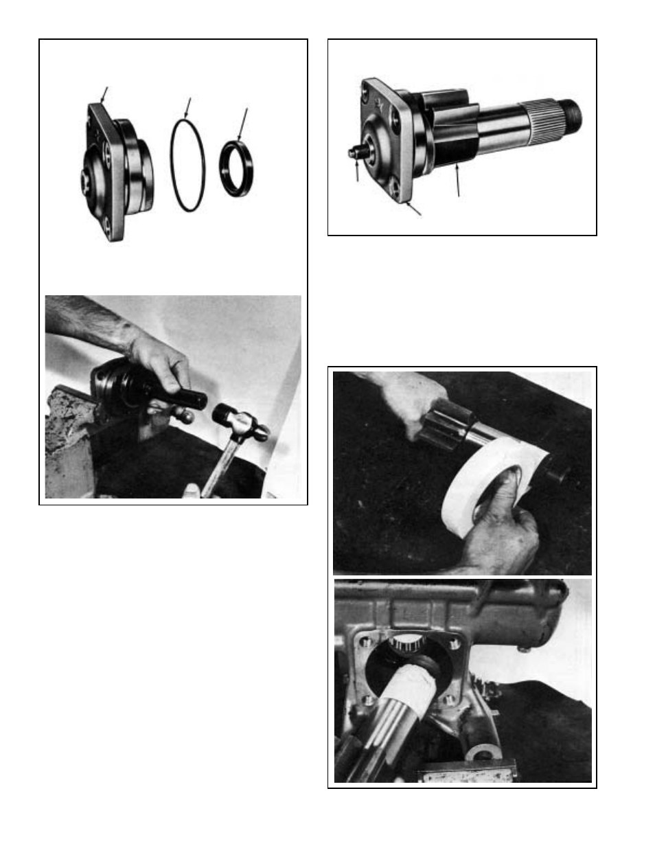
FIGURE 45
FIGURE 47
FIGURE 46
9. Install the side cover seal(39) on tool 297675 so that the
seals lip groove rests against the large diameter of the
tool. Insert the tool with the seal installed into the side
cover and using a mallet drive the seal into place. Install
the o-ring(40) in its groove on the side cover. (See Figure
45)
Pack the output shaft roller bearings in the side cover
and housing with a general purpose lithium base grease
(Ford Chassis grease ESA-M1C75-B). Lubricate the
seals in the side cover and housing using a portion of
the same grease.
10. Install the side cover(41) onto the output shaft(35). Turn
the adjusting screw(36) counterclockwise with a 9mm
socket until finger tight, then back off an eighth of a turn.
(See Figure 46)
NOTE: Be sure output shaft has contacted side cover
prior to backing off an eighth turn.
41
40
39
41
35
36
Prior to inserting the output shaft into the housing, wrap
a single layer of masking tape around the splines and
threads to protect the housing seal. Lubricate the exterior
of the tape with a lithium base grease (Ford Chassis
grease ESA-M1C75-B) and insert the shaft and side
cover assembly into the housing with a twisting motion.
(See Figure 47)