Bendix Commercial Vehicle Systems COMPACT 500 9/87 User Manual
Page 21
21
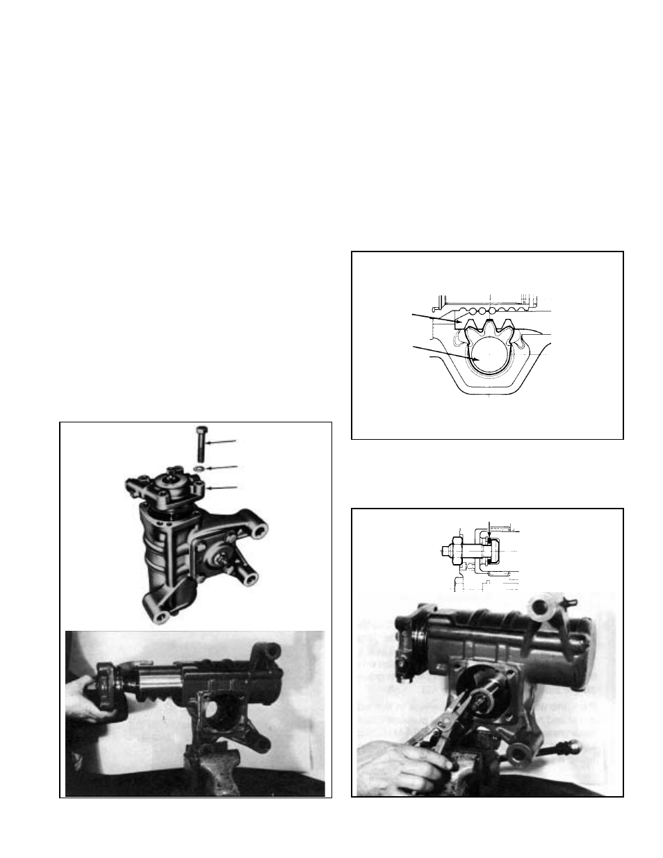
FIGURE 42
FIGURE 43
until the bearing spacer and outer race are seated against
the snap ring.
Install the seal(27) on tool 297674 so that the seals lip
groove rests against the large diameter of the tool. Next
install the thick bearing spacer on the tool making certain
the flat side of the bearing spacer rests against the seal.
(See Figures 41 E, F & G) Insert the tool with the parts
installed on it through the side cover opening and using
a mallet drive the seal into place.
Install the boot retainer(24) in the housing. Next install
the small diameter of the boot(23) into the retainer,
making certain it is fully seated within the groove formed
by the retainer.
HOUSING & VALVE BODY ASSEMBLY
7. Insert the valve body, spindle and piston assembly into
the housing making certain not to damage the O-ring
seals. Install the 4 bolts(1) and washers(2) that secure
the valve body to the housing and tighten to a torque of
96 ft.lbs. with a 22mm torque wrench.
Turn the input shaft to center the piston teeth(48) in the
side cover opening. This will facilitate the installation of
the output shaft and allow the proper mesh between the
sector and piston teeth. (See Figure 43)
8. Install into the output shaft(35), the adjusting screw(36),
the adjusting screw spacer(37) and the snap ring(38).
Spacer(37) thickness is to be selected so that the axial
play of the adjusting screw is between 0 and .0025 inch
after the snap ring is installed. (See Figure 44)
NOTE: After selecting the proper spacer(37) thickness,
disassemble it, grease the screw head with a lithium
base general purpose grease (Ford chassis grease
ESA-M1C75-B), and reassemble screw, spacer, and
snap ring.
1
2
16
OUTPUT
SHAFT
PISTON
FIGURE 44
ADJUSTING SCREW WASHER