Bendix Commercial Vehicle Systems COMPACT 500 9/87 User Manual
Page 3
3
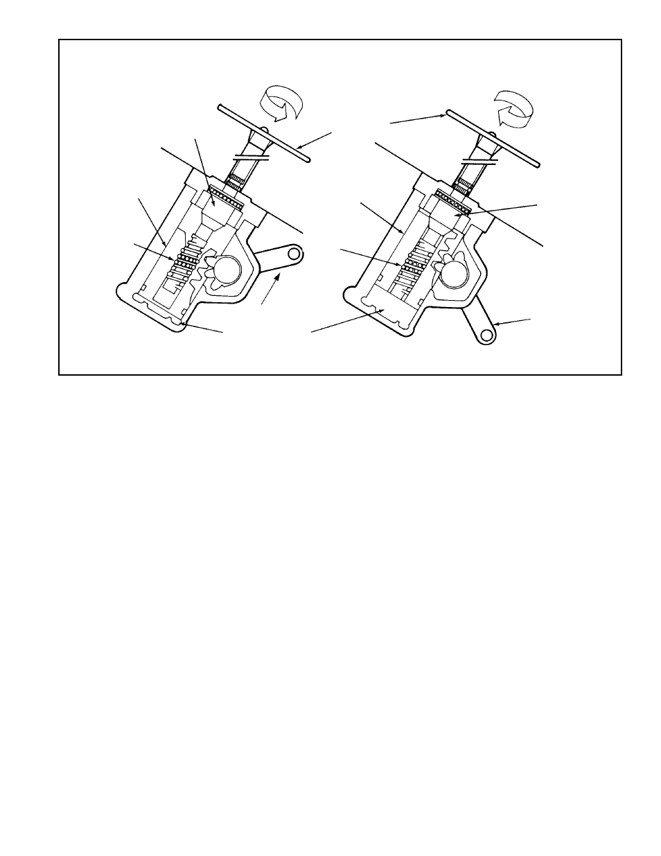
FIGURE 1 - MECHANICAL OPERATION
BALL SCREW
RECIRCULATING
BALLS
PISTON NUT
STEERING
WHEEL
SPINDLE
PITMAN
ARM
POWER CYLINDER
PITMAN ARM
PISTON NUT
RECIRCULATING
BALLS
LEFT TURN
RIGHT TURN
a screw and nut through the action of the chain of
recirculating balls that serve as an interface. Rotation of
the ball screw causes axial movement of the piston within
the power cylinder. Gear teeth cut directly into the piston
mesh with corresponding sector gear teeth on the output
shaft and as the piston moves, the output shaft and attached
pitman arm are rotated.
HYDRAULIC OPERATION
The driven end of the ball screw rotates on a ball bearing
contained in the valve body. Hydraulic pressure enters and
exits the power steering gear through lines connected to
threaded ports in the valve body. A pressure relief valve
contained in the valve body prevents overpressurization of
the power steering gear.
Hydraulic pressure in excess of the setting of the relief valve
causes the valve to open a channel to the reservoir return
side of the gear.
The ball screw assembly is retained in the valve housing by
a valve nut which forms the outermost element of the rotary
control valve. The valve nut contains circular channels and
radial passages which serve to direct hydraulic oil into and
out of the rotary control valve. The ball screw assembly forms
the rotary control and consists of three parts; the input shaft,
torsion bar, and ball screw.
One end of the input shaft is finely splined for connection to
the steering column while the other end has a coarse spline
which fits loosely with a similar spline inside the worm screw.
The coarse splines form mechanical stops which limit the
amount of relative rotation between the ball screw and input
shaft. A torsion bar connects the input shaft to the ball screw.
Six evenly distributed longitudinal grooves are machined into
the outer surface of the input shaft and correspond to six
grooves machined into the bore of the ball screw. Holes
extend from the outside surface of the ball screw into the
six grooves in the bore. These holes allow pressurized oil to
enter and exit the two inner elements of the rotary control
valve. The six grooves in the bore of the ball screw are
connected alternately to each side of the piston through
three pairs of the drilled holes. The other three holes admit
pressurized oil directly to three of the six grooves in the
input shaft. The other three grooves in the output shaft carry
oil to the return line connection. The length of the six pairs
of grooves cut into the ball screw and input shaft allows
large pressure changes to be achieved with a small rotational
displacement of the valve elements.
The rotary control valve is an open center type which allows
a continuous flow of oil (through the longitudinal grooves in
the input shaft and bore of the ball screw) when held in the
neutral position by the torsion bar. The large porting of the
valve design allows neutral position operating pressure to
remain in the 40-65 psi range which results in reduced
hydraulic pump power consumption and lower oil
temperatures.
When steering effort is applied, the input shaft and ball screw
tend to turn in unison however the spring action of the torsion