Bosch 1613AEVS User Manual
Page 9
DEPTH ROD AND TURRET
The depth rod and the depth stop turret are
used to control cutting depth as follows;
With the bit installed, gently lower the motor
until the tip of the router bit just contacts the
level surface the router is sitting on. This is
the “zero” position, from which further depth
adjustments can be accurately made. To set
a desired depth of cut, rotate depth stop
turret until the lowest step is aligned with the
depth rod. Loosen depth indicator knob and
lower the depth rod until it contacts the
lowest step of the turret. Slide the depth
indicator until the red line indicates zero on
the depth scale, indicating the point at which
the bit just contacts the work (Fig. 8).
To set a desired cutting depth, slide the depth
rod up until the red depth indicator line attains
the desired cutting depth, and secure the rod
in position by firmly tightening the depth
indicator knob. The desired depth of cut may
now be achieved by plunging the router until
the depth rod contacts the selected stop on
the turret. To be certain that your depth
settings are as desired, you may want to
make test cuts in scrap material before
beginning work. Once the desired final depth
has been set on the lowest depth turret
setting with the depth rod, it is possible to
make progressively deeper cuts by starting
with the highest step on the depth turret and
after each cut, rotating the depth turret to
progressively lower steps as desired, until the
final depth (lowest step or flat) is reached.
Steps progress by 1/8” increments.
-9-
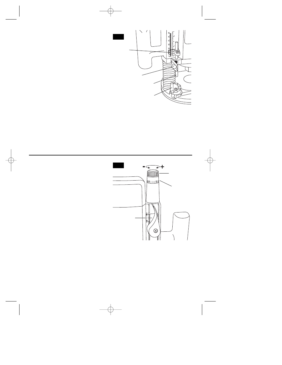
FINE ADJUSTMENT
The router is equipped with a true
micrometer-type fine adjustment mechanism,
which can be used in any plunge position and
provides precise adjustment of the router bit
position for unmatched accuracy. When the
tool is plunged to the approximate position
desired, this device may be adjusted to
precisely set the final bit position (Fig. 9).
To use the fine adjustment, turn the fine
adjustment knob clockwise to lower the
router bit or counter-clockwise to raise it. To
allow precise settings, the indicator ring is
graduated in English and Metric increments,
each line is equal to .004” or 1/10 mm. The
fine adjustment indicator may be reset to zero
without moving the fine adjustment knob, to
allow the user to begin the adjustment from
any reference point desired.
The fine adjustment mechanism has a total
adjustment range of 5/8”, which is indicated
by the index marker on the back of the
housing. Whenever the fine adjustment is
used, be certain that the index marker is
positioned between the two lines to ensure
enough travel in the desired direction after the
router is plunged into position. Note that
when the router is plunged to maximum
depth or is fully retracted to the top of the
posts, the fine adjustment knob cannot move
the motor further down or up, as the full
extension of travel has been reached.
Similarly, the fine adjustment knob cannot
lower the bit when the depth rod is tightened
against the depth turret.
1/32
3/64
FIG. 9
FINE
ADJUSTMENT
KNOB
FINE
ADJUSTMENT
INDICATOR
FIG. 8
DEPTH INDICATOR
KNOB
DEPTH
INDICATOR
DEPTH ROD
DEPTH STOP
TURRET
INDEX
MARKER
BM2610998769 10/03 10/7/03 8:18 AM Page 9