Rockwell Automation Solar Turbine Addendum Version 6.0 User Manual
Page 23
Installing Power Wiring
4-3
4.3
Installing Power Wiring from the DC Power Supply to
the Drive’s Internal DC Bus Terminals
Use the following steps to connect DC input power to the drive:
Step 1. Wire the DC input power leads by routing them according to drive type. Refer
to figures 3.2 and 3.3. Table 4.2 contains the recommended power wiring
sizes.
Step 2. Connect the DC input power leads to terminals + and – (1 HP drive) or B1
and B2 (5 HP drive) on the power terminal strip (see figure 4.2).
!
ATTENTION: Do not route signal and control wiring in the same conduit
with power wiring. This can cause interference with drive operation.
Failure to observe this precaution could result in damage to, or
destruction of, the equipment.
ATTENTION: If the GV3000/SE drive is connected to an external DC
bus, the user is responsible for DC bus short-circuit protection. Failure
to observe this precaution could result in damage to, or destruction of,
the equipment.
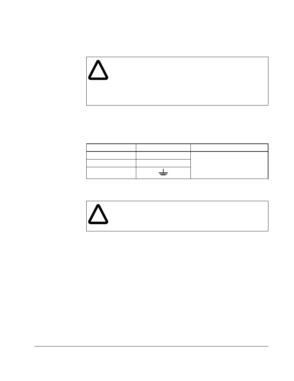
Table 4.2 – Recommended Power Wire Sizes
Type of Wiring
Terminals
Size of Wire (Maximum)
Output Power
U/T1, V/T2, W/T3
12 AWG, 3 mm
2
(1 HP)
6 AWG, 13 mm
2
(5 HP)
DC Input Power
+, –
Ground
!
ATTENTION: On the 5 HP Solar Turbine drive, the positive DC input must
be connected to the (+) terminal. The negative DC input must be
connected to the (–) terminal. These terminals cannot be interchanged.
Failure to observe this precaution could result in damage to, or
destruction of, the equipment.