Refer to, Powerflex 700s phase ii drive connections – Rockwell Automation 20D PowerFlex 700H/S Frame 13 Replacement Power Structures User Manual
Page 15
PowerFlex® 700S and 700H Frame 13 Replacement Power Structures
15
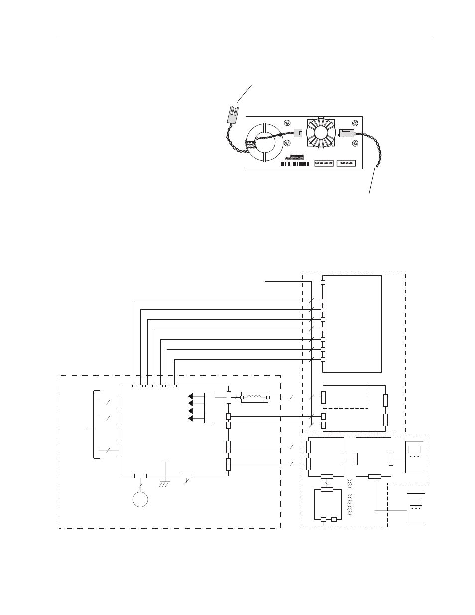
Figure 5 Termination Points on the Common Mode Filter Board
PowerFlex 700S Phase II Drive Connections:
Figure 6 Connections Between the Power Structure and the 700S Phase II Control
J5
J1
Connect to J5 on Fiber Optic
Interface Board
From Connector J8 on Power
Supply Voltage Feedback Board
HIM
J1
2
9
20
10
J2
-U
-V
-W
DC-
DC+
J8
+24V
J4 Tx
J5 Rx
X3
J3
J2
J1
X2
X1
HIM
DOOR
EXTERNAL DPI
X4
2
PWR
STS
PORT
MOD
NET A
NET B
DPI Assembly
EXAMPLE:
20-HIM-A3
20-VB00601
M6
J17
J18
J15
External
24V DC
1 = 24V
3 = Common
(75W min)
J5
J6 Tx
J7 Rx
J4
2
2
+24 V Iso
+12 V
-12 V
+5V
Pan Fan
Control
J16
Fiber Optic
Interface
Board
80W
Power
Supply
Power Supply
Voltage
Feedback
DPI
Interface
Board
DPI
Comm
Option
DPI
Bezel
Fiber Optic Cables
J8 J9 J10 J11 J12 J14 J13
M
Fiber
8
9
9
ASIC Board
H1 (Gate Enable)
H2 (U Gate)
H3 (V Gate)
H4 (W Gate)
H5 (ADconv)
H6 (Vbus Tx)
H7 (Vbus Rx)
X10
J3
40
J2
30
J1
8
Inside Power Structure
Make and verify these connections
700S Control Assembly (Phase II)
J5
J1
2
Common Mode Filter Board
To 700S Main
Control Board