Rockwell Automation Safety Function: Hinge Switch User Manual
Page 15
Safety Function: Hinge Switch
15
Rockwell Automation Publication SAFETY-AT096A-EN-P – November 2013
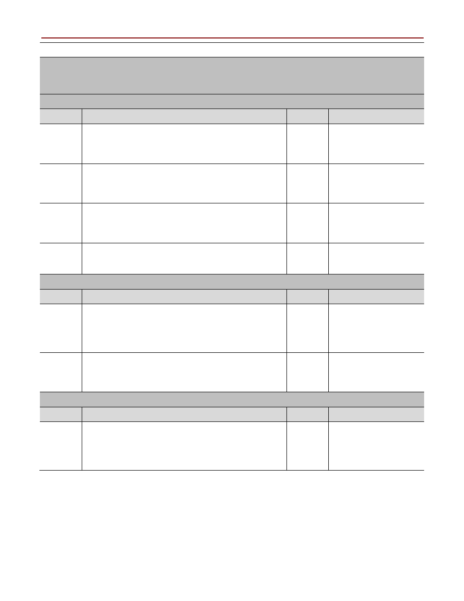
GSR Emergency Stop Safety Function Verification and Validation Checklist (continued)
Abnormal Operation Validation
The safety relay system properly responds to all foreseeable faults with corresponding
diagnostics.
E-stop Input Tests
Test Step
Validation
Pass/Fail Changes/Modification
While the system is running, remove the channel 1 wire
from the safety relay. Both contactors de-energize. Verify
proper machine-status indication and safety-relay status
indication. Repeat for channel 2.
While the system is running, short channel 1 of the safety
relay to 24V DC. Both contactors de-energize. Verify proper
machine-status indication and safety-relay status indication.
Repeat for channel 2.
While the system is running, short channel 1 of the safety
relay to 0V DC. Both contactors de-energize. Verify proper
machine-status indication and safety-relay status indication.
Repeat for channel 2.
While the system is running, short channels 1 and 2 of the
safety relay. Both contactors de-energize. Verify proper
machine-status indication and safety-relay status indication.
GSR Logic Solver Tests
Test Step
Verification and Validation
Pass/Fail Changes/Modification
While the system is running, remove the single wire safety
connection between two adjoining safety relays in the
system. All contactors de-energize. Verify proper
machine-status indication and safety-relay status indication.
Repeat for all safety connections.
While the system is running, turn the logic rotary switch on
the safety relay. All contactors remain energized. Verify
proper machine-status indication and safety-relay status
indication. Repeat for all safety relays in the system.
Safety Contactor Output Tests
Test Step
Verification and Validation
Pass/Fail Changes/Modification
While the system is running, remove the contactor feedback
from the safety relay. All contactors remain energized.
Initiate a Stop command followed by a Reset command.
The relay does not restart or reset. Verify proper
machine-status indication and safety-relay status indication.