Rockwell Automation Safety Function: Hinge Switch User Manual
Page 12
12
Safety Function: Hinge Switch
Rockwell Automation Publication SAFETY-AT096A-EN-P – November 2013
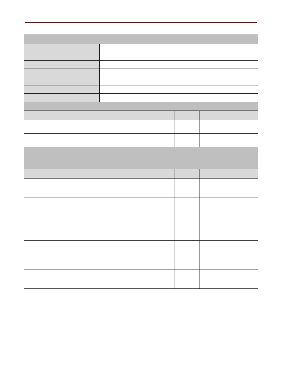
GSR Hinge Switch Safety Function Verification and Validation Checklist
General Machinery Information
Machine Name/Model Number
Machine Serial Number
Customer Name
Test Date
Tester Name(s)
Schematic Drawing Number
Guardmaster Safety Relay Model
Safety Wiring and Relay Configuration Verification
Test Step
Verification
Pass/Fail Changes/Modification
Visually inspect the safety relay circuit to verify that it is
wired as documented in the schematics.
Visually inspect the safety relay rotary switch settings to
verify they are correct as documented.
Normal Operation Verification
The safety relay system properly responds to all normal Start, Stop, Hinge Switch Input, and
Reset commands.
Test Step
Verification
Pass/Fail Changes/Modification
Initiate a Start command. Both contactors energize for a
normal machine Run condition. Verify proper
machine-status indication and safety-relay status indication.
Initiate a Stop command. Both contactors de-energize for a
normal machine Stop condition. Verify proper
machine-status and safety-relay status indication.
While the system is running, open the monitored guard
door. Both contactors de-energize and open for a normal
safe condition. Verify proper machine-status indication and
safety-relay status indication. Repeat for all guard doors.
While the system is stopped with the guard door open,
initiate a Start command. Both contactors remain
de-energized and open for a normal safe condition. Verify
proper machine-status indication and safety-relay status
indication. Repeat for all door locks.
Initiate a Reset command. Both contactors remain
de-energized. Verify proper machine-status indication and
safety-relay status indication.