Rockwell Automation Safety Function: Hinge Switch User Manual
Page 14
14
Safety Function: Hinge Switch
Rockwell Automation Publication SAFETY-AT096A-EN-P – November 2013
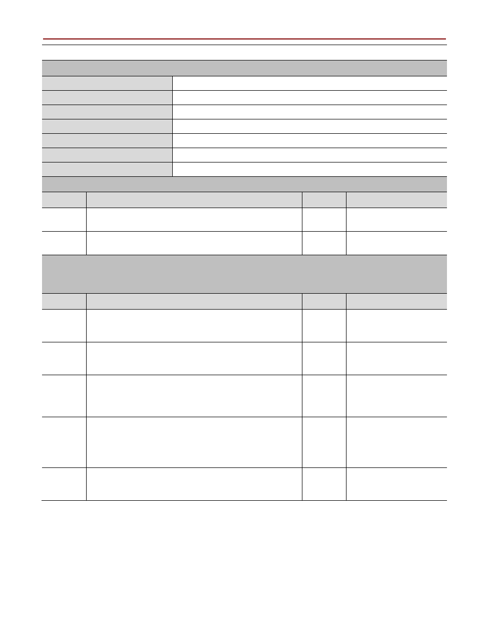
GSR Emergency Stop Safety Function Verification and Validation Checklist (continued)
General Machinery Information
Machine Name/Model Number
Machine Serial Number
Customer Name
Test Date
Tester Name(s)
Schematic Drawing Number
Guardmaster Safety Relay Model
Safety Wiring and Relay Configuration Verification
Test Step
Verification
Pass/Fail Changes/Modification
Visually inspect the safety relay circuit to verify that it is
wired as documented in the schematics.
Visually inspect the safety-relay rotary switch settings to
verify they are correct as documented.
Normal Operation Verification
The safety relay system properly responds to all normal Start, Stop, E-stop, and Reset
commands.
Test Step
Verification
Pass/Fail Changes/Modification
Initiate a Start command. Both contactors energize for a
normal machine run condition. Verify proper machine-status
indication and safety-relay status indication.
Initiate a Stop command. Both contactors de-energize for a
normal machine Stop condition. Verify proper
machine-status and safety-relay status indication.
While the system is running, press the E-stop button. Both
contactors de-energize and open for a normal safe
condition. Verify proper machine-status indication and
safety-relay status indication. Repeat for all E-stop buttons.
While the system is stopped, press the E-stop button and
initiate a Start command. Both contactors remain
de-energized and open for a normal safe condition. Verify
proper machine-status indication and safety-relay status
indication. Repeat for all E-stop buttons.
Initiate a Reset command. Both contactors remain
de-energized. Verify proper machine-status indication and
safety-relay status indication.