Module pinout connections, External i/o connector (pl1), Table 1 external i/o connector pin-out – Rockwell Automation T8110B/T8110 Trusted TMR Processor User Manual
Page 11: Trusted
Trusted
TM
TMR Processor T8110B/T8110
Issue 18 Feb 08
PD-T8110B/T8110
11
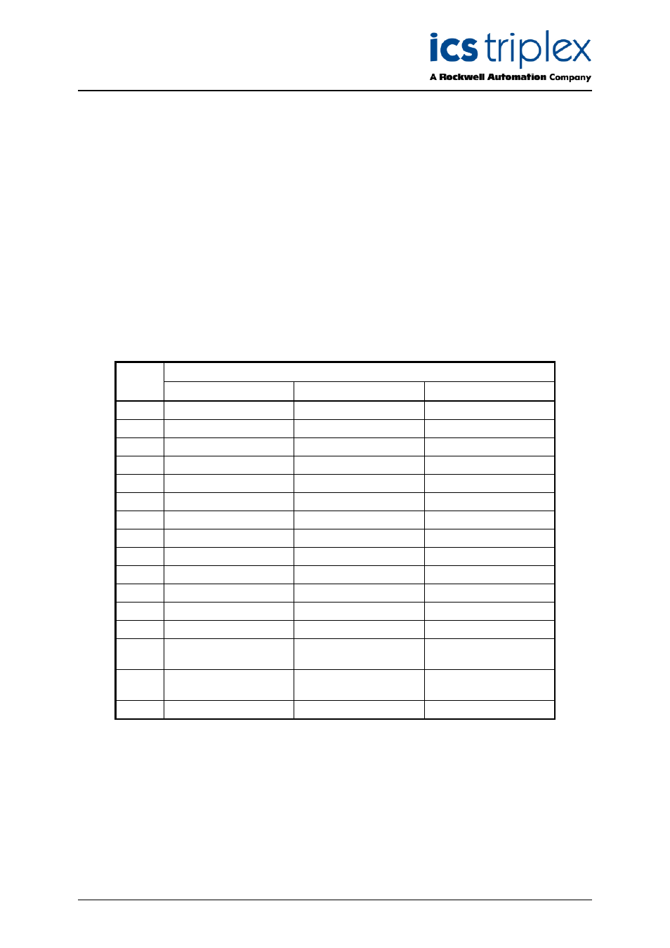
2.3. Module Pinout Connections
2.3.1. External I/O Connector (PL1)
This connector provides a number of discrete input and outputs. These are provided to allow the
Trusted
TM
TMR Processor status to be monitored by external hardware, and to allow the Trusted
TM
TMR Processor to monitor the power supply status signals. The connector also provides access to the
communications ports and connections for IRIG-B input signals. To enable the communications ports
and IRIG-B facilities to be accessed, the user must install the following:
1. Processor Interface Adaptor T8120 for the communications ports.
2. Processor Interface Adaptor Unit (IRIG-B) T8121 for both communications ports and
IRIG-B facilities
Note:
IRIG B and serial facilities are only available on the T8110B
PL1 is a 48-way DIN41612 E type connector.
Row
Pin
A
C
E
2
Fault relay (NC)
DIAG_RTN
Failed relay (NC)
4
Fault relay (common)
DIAG_IN_1
Failed relay (common)
6
Fault relay (NO)
0V Port 1
Failed relay (NO)
8
Not Connected
Serial Port 1 B
Not Connected
10
5V_D
Serial Port 1 A
IRIG-B122+
12
DATA_OUT
0V Port 2
IRIG-B122-
14
ENABLE
Serial Port 2 B TX
Reserved
16
DATA_IN
Serial Port 2 A TX
Reserved
18
CLK
Serial Port 2 B RX/TX
IRIG-B002-
20
0V
Serial Port 2 A RX/TX
IRIG-B002+
22
Chassis GND
0V Port 3
Chassis GND
24
Chassis GND
Serial Port 3 B TX
Chassis GND
26
Chassis GND
Serial Port 3 A TX
Chassis GND
28
24V PSU 1 LV Warning Serial Port 3 B RX/TX
24V PSU 1 Fail
Shutdown
30
24V PSU 2 LV Warning Serial Port 3 A RX/TX
24V PSU 2 Fail
Shutdown
32
24V Return
24V Return
24V Return
Table 1 External I/O Connector Pin-Out