Rockwell Automation SA500 AC Power Modules User Manual
Page 32
4-4
SA500 Power Modules
Step 2. Connect the DC bus wires (POS, NEG, GND) from the DC Bus Supply to the
Power Module. See figure 4.2.
The proper DC bus connection wires are provided with the Bus Supply. Do
not substitute other wires for those supplied.
Do not over-tighten the nuts on the Power Module and DC Bus terminals.
Use a nut-driver only and limit the torque to 4.0 Nm (36 lb-in).
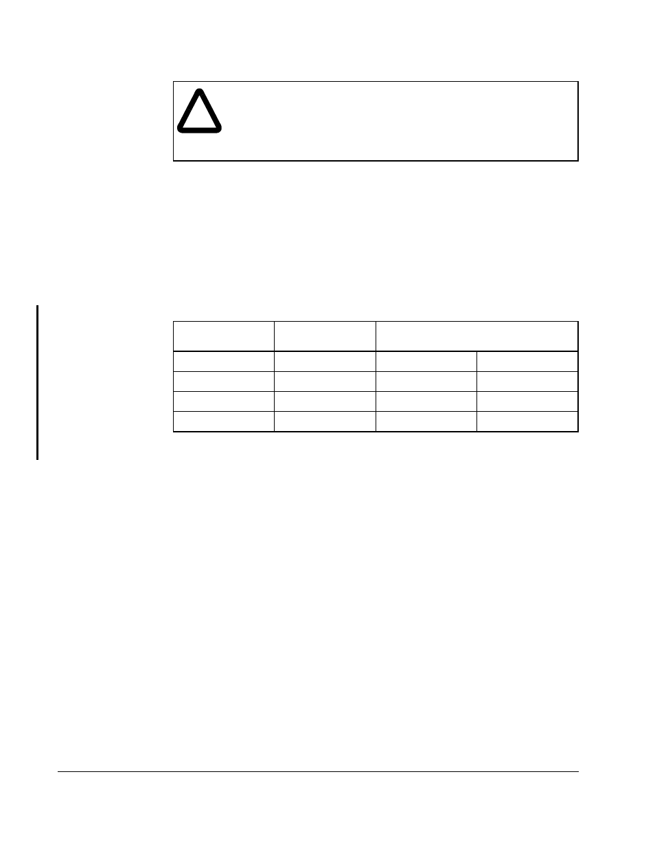
Step 3. Connect the motor wires to the Power Module’s terminals (U,V,W). See
table 4.1.
Step 4. Apply power to the input wiring of the DC Bus Supply and check the bus
voltage. It should be 325 VDC nominal. Be sure the bus voltage is present at
the Power Module’s input terminals.
!
ATTENTION: To avoid the danger of an electrical shock or burn, only
qualified personnel should install or service this equipment. Disconnect
all power before working on this equipment. Dangerous voltages may
exist after power is removed. Check the DC Bus Supply voltages each
time power is removed before servicing. Failure to observe this
precaution could result in severe bodily injury or loss of life.
Table 4.1 – Recommended Motor Wire Sizes
SA500 AC
Power Modules
Motor Terminals
Minimum
1
/Maximum
2
Wire Sizes
1. Minimum wire size required.
2. Maximum wire size allowed.
615055-1R
U-V-W,GND
4.8 / 21.6 mm
2
10 / 4 AWG
615055-1S
U-V-W,GND
4.8 / 21.6 mm
2
10 / 4 AWG
615055-1T
U-V-W,GND
8.5 / 21.6 mm
2
8 / 4 AWG
615055-1V
U-V-W,GND
13.7 / 21.6 mm
2
6 / 4 AWG